Laser energy splitting device

A laser and beam technology, applied in the direction of laser welding equipment, welding equipment, metal processing equipment, etc., can solve the problems that the laser output power cannot be realized, continuously adjustable, etc.

Active Publication Date: 2017-05-31
武汉光谷航天三江激光产业技术研究院有限公司
View PDF7 Cites 7 Cited by
  • Summary
  • Abstract
  • Description
  • Claims
  • Application Information

AI Technical Summary

Problems solved by technology

[0004] The laser energy splitting device provided in the embodiment of the present application solves the problem that the laser output power cannot be continuously adjusted by using a fixed energy splitter in the existing laser energy splitting technology, and realizes the energy splitting and

Method used


Image

  • Laser energy splitting device
  • Laser energy splitting device
  • Laser energy splitting device

Examples


Embodiment 1

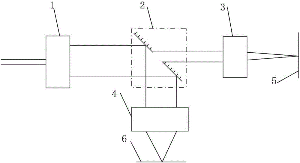
[0040] Such as figure 1 , 2 , 3 and 4, a laser energy splitting device provided by the embodiment of the present application includes a continuously adjustable beam expander 1, a beam splitter assembly 2, a first focusing assembly 3, and a second focusing assembly 4;

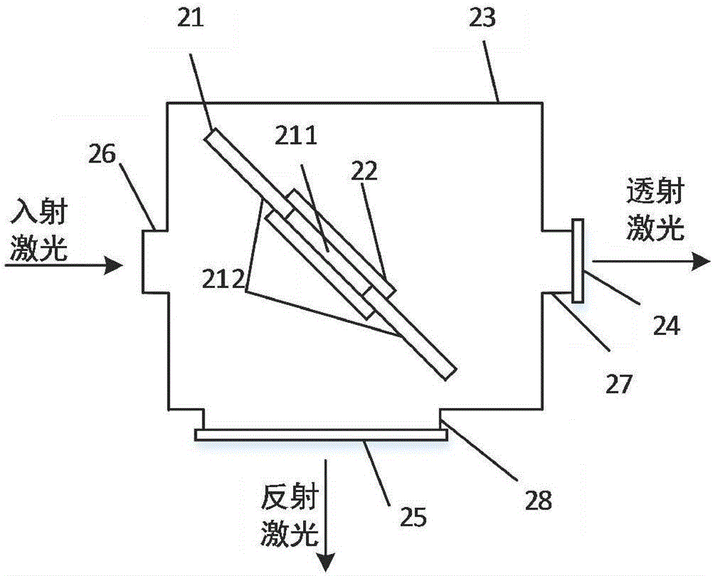
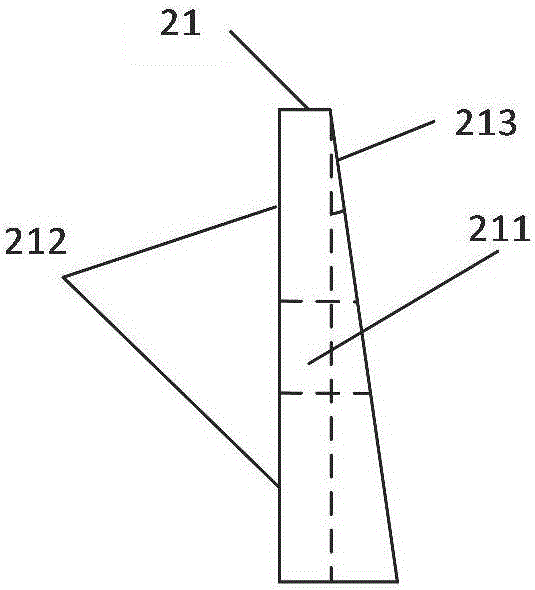
[0041] The beam splitter assembly 2 includes a hollow plane beam splitter 21 arranged obliquely to the optical axis of the incident laser, wherein the hollow plane beam splitter 21 includes a hollow transmission part 211 and a specular reflection part 212;

[0042] The continuously adjustable beam expander 1 expands the collimated incident laser beam and emits a collimated beam, and the beam expansion ratio is continuously adjustable;

[0043] The hollow planar beam splitter 21 divides the output beam of the continuously adjustable beam expander into at least two paths, one path is transmitted to the first focusing assembly 3 through the hollow transmission part 211, and the other path is reflected by the mirro...

Embodiment 2

[0061] The technical solution of this embodiment is further described in one of practical ways below:

[0062] A laser energy splitting device, such as attached figure 1 , 2 , 3, and 4, including a continuously adjustable beam expander 1, a beam splitter assembly 2, a first focusing assembly 3 and a second focusing assembly 4 respectively located in the reflection and transmission optical paths; the continuously adjustable beam expander 1 The beam expansion ratio can be adjusted continuously; the beam splitter assembly 2 includes a hollow plane beam splitter whose normal line forms an angle of 45° with the incident optical axis and its fixing assembly, wherein the laser beam passes through the hollow part of the hollow plane beam splitter Transmission and partial reflection by the mirror surface, the angle between the normal of the hollow planar beam splitter and the incident optical axis of 45° is an optimal reference value, which can be adjusted according to the actual opti...


PUM


Abstract

The invention relates to the technical field of laser energy splitting and provides a laser energy splitting device. The laser energy splitting device comprises a continuous adjustable beam expanding lens, a beam splitter component, a first focusing component and a second focusing component, wherein the beam splitter component comprises a hollow planar beam splitter obliquely arranged relative to the optical axis of incident laser, and the hollow planar beam splitter comprises a hollow transmission part and a mirror-surface reflection part; the continuous adjustable beam expanding lens aligns with the incident laser to perform bean expanding, and the beam expanding ratio is continuous and adjustable; the collimated light beam after the beam expanding enters the hollow planar beam splitter and is split into at least two light beams, one light beam is transmitted to the first focusing component through the hollow transmission part, and the other light beam is reflected to the second focusing component through the mirror-surface reflection part. The laser energy splitting device has the advantages that the problem that the output power of a fixed energy splitter in the existing laser energy splitting technology cannot be adjusted is solved, continuous adjusting of the energy splitting and the energy splitting ratio of optional-polarization-state lasers is achieved, and the energy splitting application requirements of the research and development field of laser processing production and process requiring continuous and adjustable output power are satisfied.

Description

technical field [0001] The invention relates to the technical field of laser energy distribution, in particular to a laser energy distribution device. Background technique [0002] Laser processing has the advantages of fast speed, no noise and non-contact processing, and is widely used in laser drilling, welding, cutting, marking and other fields; in the field of high-power laser processing, in order to improve work efficiency and equipment integration, through It becomes necessary to carry out multi-channel processing by laser division. [0003] The fixed energy splitter used in the prior art uses partially transmissive and partially reflective mirrors or prisms to realize laser beam splitting. The structure is simple and reliable, but it does not satisfy the fields of laser processing and production and process research and development with continuously adjustable output power. Contents of the invention [0004] The laser energy splitting device provided in the embodim...

Claims


Application Information

Patent Timeline
IPC IPC(8): B23K26/067
CPCB23K26/0673
Inventor 何崇文刘娟娟王斐范小康李立坤余海龙许学军
Owner 武汉光谷航天三江激光产业技术研究院有限公司
Why Eureka
Try Eureka