Platinum channel mixing barrel and platinum channel mixing barrel device

A platinum channel and mixing tank technology, applied in the field of glass substrate production equipment, can solve problems affecting the normal operation of the production line, temperature influence, and restricting the improvement of the glass yield rate of the production line substrate

Active Publication Date: 2017-05-31
DONGXU OPTOELECTRONICS TECH CO LTD
View PDF8 Cites 12 Cited by
  • Summary
  • Abstract
  • Description
  • Claims
  • Application Information

AI Technical Summary

Problems solved by technology

However, the temperature in the mixing tank area will be greatly affected during the cleaning or replacement process, and a large amount of volatiles will fall into the glass liquid in the mixing tank during the cleaning or replacement process, which will cause a large number of defects. Among them, the precious metal defects will sink to the bottom of the mixing tank due to the specific gravity, and it will take several days or even weeks to be taken away by the molten glass, which seriously affects the normal operation of the production line and restricts the quality of the production line substrate glass. rate increase and increased equipment replacement costs

Method used


Image

  • Platinum channel mixing barrel and platinum channel mixing barrel device
  • Platinum channel mixing barrel and platinum channel mixing barrel device

Examples


Embodiment 1

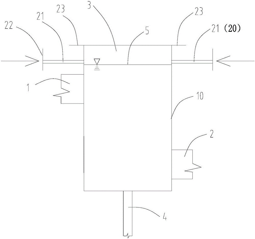
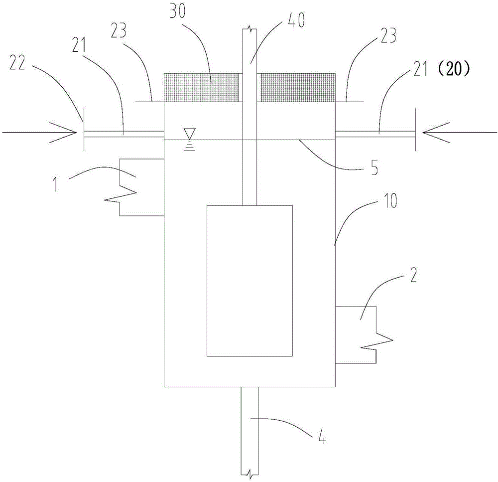
[0056] use figure 2 The platinum channel mixing barrel device shown is tested. The inert gas is nitrogen, the temperature when the inert hot gas enters the space above the free liquid level is 1000℃, and the flow rate is 2m 3 / h, the flow of glass liquid in the mixing barrel is 400kg / h. The stirring barrel body 10, the stirring rod 40, the first electrode 22, the second electrode 23, the discharge port 4, and the inert gas blowing pipe 21 are all made of platinum rhodium alloy. The inert gas blowing pipe 21 is a circular pipe with an inner diameter of 16 mm. The test time is 10 months.

experiment example 2

[0057] Experimental example 2, using figure 2 The platinum channel mixing barrel device shown is tested. The inert gas is nitrogen, the temperature when the inert hot gas enters the space above the free liquid level is 1200℃, and the flow rate is 5m 3 / h, the flow of glass liquid in the mixing barrel is 400kg / h. The stirring barrel body 10, the stirring rod 40, the first electrode 22, the second electrode 23, the discharge port 4, and the inert gas blowing pipe 21 are all made of platinum rhodium alloy. The inert gas blowing pipe 21 is a circular pipe with an inner diameter of 16 mm. The test time is 10 months.

experiment example 3

[0058] Experimental example 3, using figure 2 The platinum channel mixing barrel device shown is tested. The inert gas is nitrogen, the temperature when the inert hot gas enters the space above the free liquid surface is 1300℃, and the flow rate is 8m 3 / h, the flow of glass liquid in the mixing barrel is 400kg / h. The stirring barrel body 10, the stirring rod 40, the first electrode 22, the second electrode 23, the discharge port 4, and the inert gas blowing pipe 21 are all made of platinum rhodium alloy. The inert gas blowing pipe 21 is a circular pipe with an inner diameter of 16 mm. The test time is 10 months.


PUM

PropertyMeasurementUnit
areaaaaaaaaaaa

Abstract

The invention relates to a platinum channel mixing barrel and a platinum channel mixing barrel device. The platinum channel mixing barrel comprises a stirring barrel body with a barrel opening, a molten glass inlet and a molten glass outlet, wherein the mixing barrel body is also communicated with a hot-gas supply device for blowing an inert hot gas into a space above a free water surface in the mixing barrel body, so that the inert hot gas blown by the hot-gas supply device flows into the space above the free water surface and then is sent out from the barrel opening. Oxygen in the space is diluted and discharged by blowing the inert hot gas into the space above the free water surface in the mixing barrel body, so that volatilization of a precious metal component exposed in the space is inhibited and a precious metal volatile matter of generating precious metal defects is reduced from the source. The generated precious metal volatile matter can be taken out of the space along with continuous injection of the inert hot gas into the space above the free water surface, and the condensation of the precious metal volatile matter can be reduced, so that the probability of generating the precious metal defects in a glass substrate is reduced and the yield and the quality of a product are improved.

Description

Technical field [0001] The present disclosure relates to the field of glass substrate production equipment, and in particular to a platinum channel stirring barrel and a platinum channel stirring barrel device. Background technique [0002] In the glass substrate manufacturing process, the furnace process melts the batch materials into molten glass and then reaches the platinum channel process for clarification and homogenization. The molten glass passes through the platinum channel process and then is sent to the forming process to be made into a glass substrate semi-finished product. After the semi-finished product is processed The finished product is then packaged and transported to the panel manufacturer for use. [0003] Due to the development of demand in the consumer market, panel manufacturers have followed closely the display accuracy of panels and the market’s pursuit of ultra-thin products. In turn, the requirements for glass substrates have become higher and higher. As ...

Claims


Application Information

Patent Timeline
Patent Type & Authority Applications(China)
IPC IPC(8): C03B5/225
CPCC03B5/225Y02P40/57
Inventor 田红星郑权
Owner DONGXU OPTOELECTRONICS TECH CO LTD
Why Eureka
Try Eureka