Stepless speed regulation hydraulic drive system of screw conveyor for super large diameter shield tunneling machine

A screw conveyor, super-large diameter technology, applied in the field of stepless speed regulation hydraulic drive system for super-large diameter shield screw conveyor, can solve the problems of insufficient muck conveying capacity, insufficient rescue torque, small driving torque, etc. The effect of wide range, novel design and guaranteed stability

Active Publication Date: 2018-03-30
CHINA RAILWAY ENGINEERING EQUIPMENT GROUP CO LTD
View PDF7 Cites 0 Cited by
  • Summary
  • Abstract
  • Description
  • Claims
  • Application Information

AI Technical Summary

Problems solved by technology

[0003] Aiming at the deficiencies in the prior art, the present invention provides a stepless speed-regulating hydraulic drive system for a super-large-diameter shield screw conveyor, which solves the problems of small driving torque, insufficient escape torque, and high speed in the current large-diameter shield screw conveyor drive system. It can adapt to the working conditions of high torque and high speed, and at the same time, it can realize functions such as stepless speed regulation, overload protection, two-way rotation, etc., with stable operation performance and good use effect

Method used


Image

  • Stepless speed regulation hydraulic drive system of screw conveyor for super large diameter shield tunneling machine
  • Stepless speed regulation hydraulic drive system of screw conveyor for super large diameter shield tunneling machine
  • Stepless speed regulation hydraulic drive system of screw conveyor for super large diameter shield tunneling machine

Examples


Embodiment 1

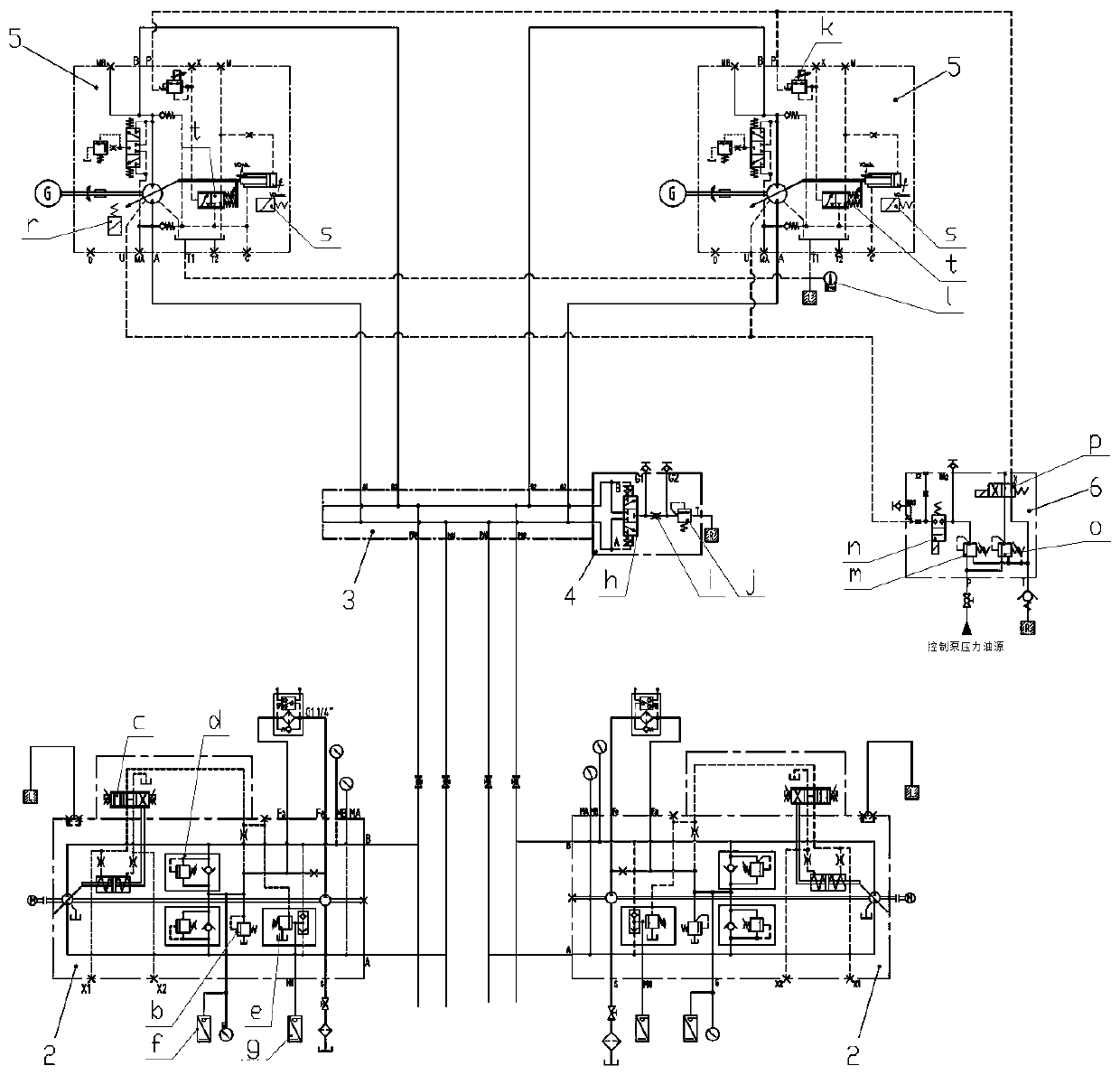
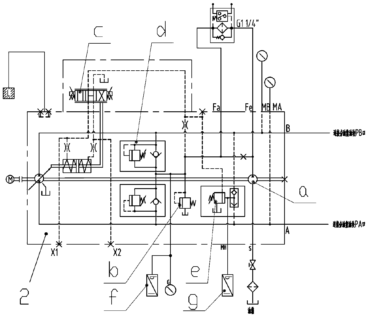
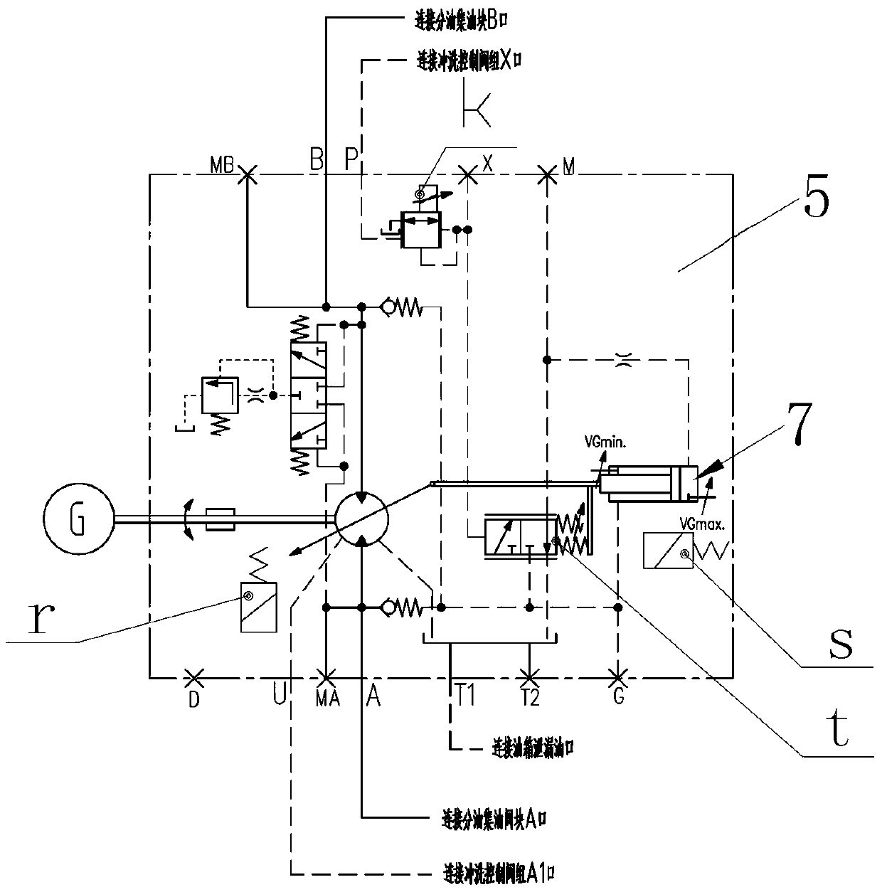
[0024] Embodiment one, see figure 1 As shown, a stepless speed-regulating hydraulic drive system for a screw conveyor for super-large-diameter shield tunneling, including a fuel tank, a hydraulic pump set, a speed-regulating hydraulic circuit, a reducer, a hydraulic motor set, and a control unit. The hydraulic circuit is connected with the hydraulic motor group. The speed regulating hydraulic circuit is equipped with an oil separation and collection valve module, a flushing control valve module, a control pump, and a sensor module. The oil separation and collection valve module, the flushing control valve module and the sensor module are all connected to the The control unit is connected by communication. The hydraulic pump group includes hydraulic pump 1 and hydraulic pump 2. The hydraulic pump 1 and hydraulic pump 2 are connected to the hydraulic motor group through the oil separation and oil collection valve module. The hydraulic pump 1, hydraulic pump Pump 2 is provided wi...

Embodiment 2

[0026] Embodiment two, see Figure 1~5 As shown, it is basically the same as Embodiment 1, except that the oil separation and collection valve module also includes a hot oil valve group, and the hot oil valve group is connected to the oil tank.

[0027] Preferably, the hot oil valve group includes hot oil valve 1 and hot oil valve 2; said hot oil valve 1 and hot oil valve 2 both include: hydraulic control valve, back pressure valve, hydraulic control valve control end and hydraulic motor group The other end of the hydraulic control valve is connected to the back pressure valve, and a damping hole is also arranged on the connecting pipeline between the hydraulic control valve and the back pressure valve, and the outlet end of the back pressure valve is connected to the fuel tank through the oil return pipeline.

[0028] Above, hydraulic pump 1 and hydraulic pump 2 are both swash plate axial piston pumps. see figure 1 As shown in , the oil separation and collection valve modul...


PUM


Abstract

The invention relates to a stepless speed-regulating hydraulic drive system for a screw conveyor for super-large-diameter shield tunneling, which includes a fuel tank, a hydraulic pump group, a speed-regulating hydraulic circuit, a reducer, a hydraulic motor group, and a control unit. There are oil separation and oil collection valve modules, flushing control valve modules, control pumps, and sensor modules. The hydraulic pump group includes hydraulic pump 1 and hydraulic pump 2. Both hydraulic pump 1 and hydraulic pump 2 are equipped with displacement adjustment mechanisms , the hydraulic motor group includes hydraulic motor 1 and hydraulic motor 2 that operate synchronously, and hydraulic motor 1 and hydraulic motor 2 are both provided with an output variable adjustment mechanism, and the displacement adjustment mechanism and output variable adjustment mechanism are all communicated with the control unit . The present invention can satisfy the hydraulic drive system with high torque and high rotational speed, realize the functions of variable speed adjustment, overload protection, and bidirectional rotation, is safe and reliable, and effectively guarantees the stability of the operation performance of the screw conveyor.

Description

technical field [0001] The invention relates to the technical field of hydraulic control of screw conveyors, and relates to a stepless speed-regulating hydraulic drive system for screw conveyors for super-large-diameter shield tunneling machines, which can meet the needs of large-torque, high-speed screw conveyor drive systems for super-large-diameter shield machines. need. Background technique [0002] At present, the screw conveyor, as one of the key components of the shield machine, mainly transports the muck in the excavated soil bin to the muck transfer system such as the belt conveyor. The driving mechanism of the screw conveyor of the existing shield machine is driven by a hydraulic motor, the output torque is small, and the excavation capacity is low, which seriously affects the speed of the whole machine in the construction of the shield machine and increases the construction cost and other problems. The reliability and high efficiency of the screw conveyor are rel...

Claims


Application Information

Patent Timeline
Patent Type & Authority Patents(China)
IPC IPC(8): F15B11/17F15B13/06F15B20/00F15B21/08B65G33/34
CPCB65G33/34F15B11/17F15B13/06F15B20/00F15B21/087F15B2211/20546F15B2211/20576F15B2211/865
Inventor 陈良武李光赵康峰齐保卫曾翔周小磊朱雷詹晨菲孙向前
Owner CHINA RAILWAY ENGINEERING EQUIPMENT GROUP CO LTD
Why Eureka
Try Eureka