Test method and tester for high frequency pulse signal
A high-frequency pulse and pulse signal technology, applied in the field of electronic signal parameter testing, can solve the problem of not being able to fully grasp the pulse signal, and achieve the effect of high-precision and fast measurement
- Summary
- Abstract
- Description
- Claims
- Application Information
AI Technical Summary
Problems solved by technology
Method used
Image
Examples
Embodiment 1
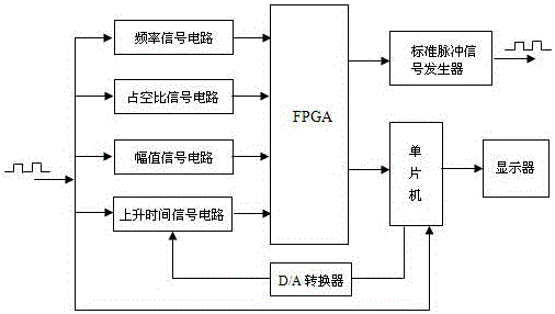
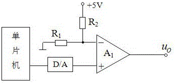
[0026] like figure 1 Shown is the structural block diagram of the high-frequency pulse signal tester of the present invention. The high-frequency pulse signal tester includes: frequency, duty cycle, and amplitude signal conditioning circuit, which is used to adjust the frequency, duty cycle, and amplitude of the input signal. The rise time signal conditioning circuit is used for conditioning the rise time of the input signal. The FPGA receives the signals output by each conditioning circuit, and measures the parameters of the high-frequency pulse signal, including frequency, duty cycle and rise time. The single-chip microcomputer measures the amplitude of the high-frequency pulse signal, and receives the measurement data of the FPGA in real time for data analysis. The single-chip microcomputer is connected to the rise time signal conditioning circuit through a D / A converter, and provides two threshold voltages for the rise time signal conditioning circuit. The measured high-...
Embodiment 2
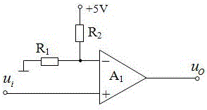
[0028] like figure 2 As shown, the frequency, duty cycle and amplitude signal conditioning circuit of this embodiment uses a rail-to-rail high-speed comparator TLV3501 to shape the input pulse signals of different amplitudes into a square wave signal of 0-3.3V, and then input it into the FPGA. FPGA counts the standard pulse signal and the measured high-frequency pulse signal respectively within the gate time, and then calculates the frequency of the measured high-frequency pulse signal according to the count value of the two counters and the frequency of the standard pulse signal. In order to improve the sensitivity of the instrument and the maximum measurement range of the frequency, the gate time is set to 1s, and the standard pulse signal is generated by the standard pulse signal generator, which is a 1MHz clock signal.
[0029] MSP430 single-chip microcomputer is used, which can realize the instruction cycle of 40ns under the drive of 25MHz crystal, so as to realize the f...
PUM
 Abstract
Description
Claims
Application Information
 - R&D
- Intellectual Property
- Life Sciences
- Materials
- Tech Scout
- Unparalleled Data Quality
- Higher Quality Content
- 60% Fewer Hallucinations
Browse by: Latest US Patents, China's latest patents, Technical Efficacy Thesaurus, Application Domain, Technology Topic, Popular Technical Reports.
© 2025 PatSnap. All rights reserved.Legal|Privacy policy|Modern Slavery Act Transparency Statement|Sitemap|About US| Contact US: help@patsnap.com


