Flexible direct current distribution system fault positioning method based on traveling wave

A technology for flexible DC power distribution and system faults, which is applied in fault locations, information technology support systems, and fault detection according to conductor types. It can solve the problems of short response time, increased redundancy, and low precision, and achieve fault accuracy The effect of positioning, improving calculation speed, and ensuring calculation accuracy

Inactive Publication Date: 2017-05-31
BEIJING JIAOTONG UNIV
View PDF6 Cites 16 Cited by
  • Summary
  • Abstract
  • Description
  • Claims
  • Application Information

AI Technical Summary

Problems solved by technology

Paper: DC Fault Protection Scheme for Multi-terminal Flexible DC System [J]. Chinese Journal of Electrical Engineering, 2016, 36(0): 1-10, Paper: Research on Fault Isolation Technology of Multi-terminal Flexible DC Power Grid [J]. Chinese Journal of Electrical Engineering, 2016 ,36(1):87-95, the above papers researched the protection and isolation of multi-terminal ring flexible DC systems, which promoted the research process of flexible DC systems, but did not mention the method of fault location
Paper: Wavelet-based protection strategy for DC faults in multi-terminal VSC HVDC systems[J]. IET Generation, Transmission & Distribution, 2011, 5(4), 496-503, by selecting two out of three monitoring standards, Increased reliability, but with a corresponding increase in redundancy
Paper: New faultlocation approach using voltage measurements[C]//Proceedings 2007IEEESoutheastCon, March 407-412, 2007, Richmond, VA, by combining the voltage information at the busbar with the network results to form the busbar impedance matrix technology for fault location, although this method It can also achieve high accuracy,

Method used


Image

  • Flexible direct current distribution system fault positioning method based on traveling wave
  • Flexible direct current distribution system fault positioning method based on traveling wave
  • Flexible direct current distribution system fault positioning method based on traveling wave

Examples


Embodiment Construction

[0017] The specific embodiment of the present invention is described below in conjunction with accompanying drawing:

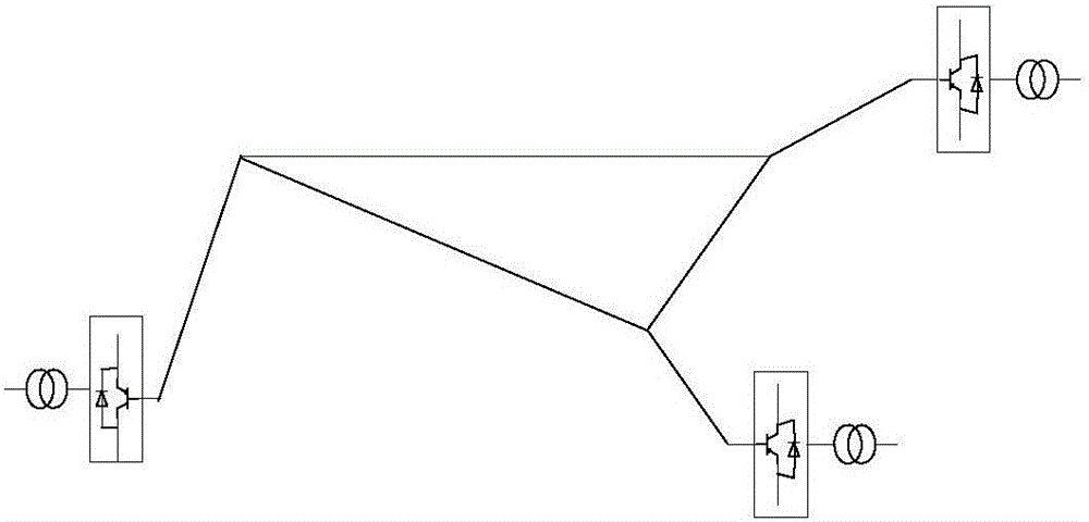
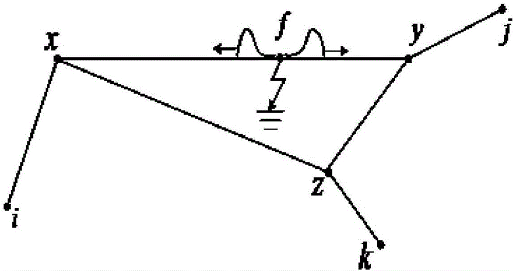
[0018] The present invention adopts the principle of double-terminal traveling wave ranging, assuming that figure 1 The two endpoints of the line shown are equipped with measuring equipment with high sampling rate and synchronized with GPS signals, then at the arrival time of the initial wave head of each detector and the shortest path of the traveling wave head along the fault point f to each detector related. Therefore, it is only necessary to detect the time (t x and t y ), the location of the fault point can be obtained.

[0019] For multi-terminal ring flexible DC power distribution systems (including grid and radial lines), the problem of fault location will become more complicated due to the large number of nodes and branches. Different from the fault location of the transmission line at both ends, in the multi-terminal DC system, the shortest path ...


PUM


Abstract

The invention discloses a flexible direct current distribution system fault positioning method based on a traveling wave, and belongs to the technical field of the distribution system fault positioning method. The invention presents a multi-port looped network type flexible direct current system fault positioning method based on the minimum fault time of the travelling wave specific to a complex structure of a multi-port flexible direct current system and the transmission characteristics of the travelling wave. The network topology of the complex multi-port flexible direct current system is expressed by a picture. And then it can be judged if the fault happens on a radiation line or the inner part of the looped network. For the fault at the inner part of the looped network, the fault starting moment when every line goes wrong is calculated and compared, thus the fault branch is found, and the fault point is calculated. The flexible direct current distribution system improves the calculation speed of the algorithm on the basis of guaranteeing the calculation precision; it is very important to the direct current network of which response time is much more than that of the alternating current system.

Description

technical field [0001] The invention specifically relates to a fault location method for a flexible DC power distribution system based on traveling waves, and belongs to the technical field of fault location methods for power distribution systems. Background technique [0002] With the rapid development of power electronics technology, the extensive access of new energy in the power grid, and the continuous increase of DC loads such as electric vehicles, information equipment and semiconductor lighting systems, DC power grids have achieved technical and economic advantages in many aspects . After a fault occurs in the line of the flexible DC transmission and distribution system, quickly and accurately locate the fault point, which is not only of great significance for quickly repairing the faulty line, ensuring the reliability of power supply and reducing power loss, but also for ensuring the safe, stable and economical operation of the entire power system. All have a very ...

Claims


Application Information

Patent Timeline
IPC IPC(8): G01R31/08
CPCG01R31/086G01R31/088Y04S10/52
Inventor 罗国敏林琦智和敬涵
Owner BEIJING JIAOTONG UNIV
Why Eureka
Try Eureka