Short-wave, long-wave and infrared dual-band focal plane-shared large-relative aperture optical system

A long-wave infrared and optical system technology, applied in optics, optical components, cameras, etc., can solve the problems of increasing the difficulty of processing and assembling the three-mirror system, the lack of engineering feasibility of the optical system, and strict tolerances of the optical system. Achieve the effect of miniaturization, light weight and integration, uniform distribution of relative illuminance on the image plane, and small size

Active Publication Date: 2017-05-31
XI'AN INST OF OPTICS & FINE MECHANICS - CHINESE ACAD OF SCI
View PDF3 Cites 9 Cited by
  • Summary
  • Abstract
  • Description
  • Claims
  • Application Information

AI Technical Summary

Problems solved by technology

The transmissive optical system disclosed in the article has an F-number of 1.4 or 1.6 when the focal length is 50 mm, and at least three aspherical surfaces are used, and some designs also use diamond, cesium iodide (CsI), Materials such as cesium bromide (CsBr) that are difficult to process or have unstable physical and chemical properties make the entire optical system lack engineering feasibility; another lens design using a catadioptric structure has an F number of 10000 at a focal length of 50mm. 1.3
Although the lens only uses two pieces of multi-spectral ZnS lenses, each optical reflection surface and transmission surface of the lens are processed on two pieces of ZnS lenses, and the lens also contains Mankin mirror elements, which will lead to strict tolerances of the entire optical system , the processing is more difficult, and the larger central occlusion also reduces the light energy utilization rate of the entire system, which to a large extent offsets the advantages of the small F number of the lens; in addition, this document also announced a three-dimensional Reflective optical design, the focal length of the entire optical system is 50mm, and the F number is 1.9. Although the entire system has no central obstruction and is compact, it still has a larger volume than the transmissive system, and the three reflective surfaces are all Zernike surfaces. It also increases the difficulty of processing and assembling the three-anti system

Method used


Image

  • Short-wave, long-wave and infrared dual-band focal plane-shared large-relative aperture optical system
  • Short-wave, long-wave and infrared dual-band focal plane-shared large-relative aperture optical system
  • Short-wave, long-wave and infrared dual-band focal plane-shared large-relative aperture optical system

Examples


Embodiment 1

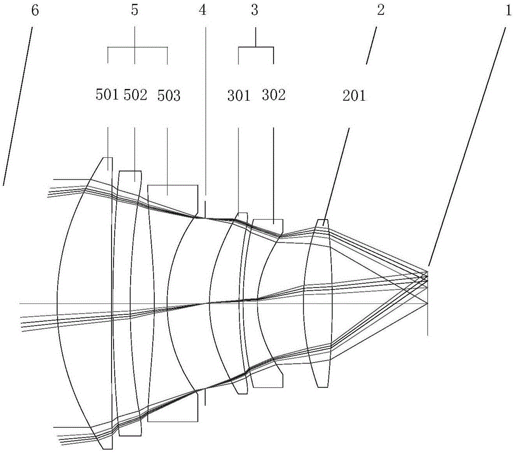
[0039] figure 1 An implementation example of a short-wave infrared and long-wave infrared dual-band confocal surface large relative aperture optical system is described. exist figure 1 In the described short-wave infrared and long-wave infrared confocal surface large relative aperture optical system, the lens structure mainly includes: from the object side 6 to the focal plane 1, the front fixed mirror group 5, the diaphragm 4, and the middle fixed mirror are arranged and fixed in order. Group 3 and rear fixed mirror group 2. Wherein, the front fixed lens group 5 has a positive refractive power and is a three-separated three-piece structure, consisting of a first positive lens 501 using ZnS material, a first negative lens 502 using CdTe material and a second negative lens 503 using BaF2 material Composition; the middle fixed mirror group 3 contains two lenses with negative refractive power, which is paired and combined by the second positive lens 301 using ZnSe material and ...

Embodiment 2

[0052] The confocal short-wave and long-wave infrared confocal large relative aperture optical system in this embodiment satisfies the technical conditions of the first embodiment above, and at the same time, a filter F is added between the rear fixed mirror group 2 and the focal plane 1 . Please refer to the schematic diagram of the specific optical lens structure Figure 4 .

[0053] In this embodiment, the filter F can be a series of filters with different transmission bands, which are fixedly connected to the filter frame, or the filter wheel, or other filters that can ensure that the imaging system can achieve light filtering during the working process. On the mechanism of film switching, cooperate with the short-wave and long-wave dual-band imaging components, and manually or electrically switch the filters with different transmission bands to complete the multi-spectral imaging of the target or scene.

[0054] The industrial availability of the short-wave infrared and ...


PUM


Abstract

The present invention provides a large-relative aperture optical system. The large-relative aperture optical system has the advantages of few consumed materials, small size and compact structure, and can effectively eliminate inter-band and intra-band chromatic aberration in a dual-band system. The optical system includes a front fixed lens assembly, an diaphragm, an intermediate fixed lens assembly, a rear fixed lens assembly and a detector which are sequentially distributed from an object side to a focal plane and are fixedly connected with one another; the front fixed lens assembly, the diaphragm, the intermediate fixed lens assembly and the rear fixed lens assembly share the same central axis; the front fixed lens assembly has positive focal power and comprises a first positive lens, a first negative lens and a second negative lens which are distributed sequentially along the central axis from the object side to the focal plane coaxially; the intermediate fixed lens assembly has negative focal power and comprises a second positive lens and a third negative lens which are distributed sequentially along the central axis from the object side to the focal plane coaxially; the diaphragm is located between the third negative lens and the second positive lens; and the rear fixed lens assembly is a third positive lens.

Description

technical field [0001] The present invention relates to an optical system design for two bands of short-wave infrared and long-wave infrared, in particular to a common optical path confocal surface using only transmission elements and including two bands of short-wave infrared 0.9 μm-1.7 μm and long-wave infrared 8 μm-12 μm optical system design. Background technique [0002] Like visible light imaging, near-infrared imaging is usually the detection of radiation reflected from targets or backgrounds. However, due to the longer wavelength of the latter, it is less affected by atmospheric scattering, the working distance can be longer, and the latter has better smoke penetration ability, which makes near-infrared imaging have better environmental adaptability; long-wave infrared imaging It is mainly to detect the radiation characteristics of the object itself. It is an ideal band for detecting the infrared characteristics of the target in a specific background. At the same ti...

Claims


Application Information

Patent Timeline
Patent Type & Authority Applications(China)
IPC IPC(8): G02B13/14G02B7/00G03B11/00
CPCG02B7/006G02B13/14G03B11/00
Inventor 曲锐杨洪涛梅超曹剑中
Owner XI'AN INST OF OPTICS & FINE MECHANICS - CHINESE ACAD OF SCI
Why Eureka
Try Eureka