Method for rapidly and accurately measuring low angle grain boundary orientation under transmission electron microscope

An electron microscope and precise measurement technology, applied in the direction of material analysis using radiation diffraction, etc., can solve problems such as troublesome, cumbersome data processing, and not many, and achieve the effect of simple calculation formula, convenient calculation, and simple operation

Active Publication Date: 2017-06-06
YANSHAN UNIV
View PDF3 Cites 11 Cited by
  • Summary
  • Abstract
  • Description
  • Claims
  • Application Information

AI Technical Summary

Problems solved by technology

The three methods have their own advantages and disadvantages. The early Kikuchi line + projection diagram method is simple to measure, but the later result processing is more troublesome, and requires the tester to have a crystallographic foundation; ASTAR technology is a newly emerging measurement technology. The advantage is that both operation and analysis It is automatic control and easy to operate, but this method needs to install expensive hardware and software on the transmission electron microscope; while the electron microscope tilting technology needs to tilt the three band axes of each grain to the positive band axis direction, Due to the complexity of the test and the cumbersome processing of later experimental data, it is not used much

Method used


Image

  • Method for rapidly and accurately measuring low angle grain boundary orientation under transmission electron microscope
  • Method for rapidly and accurately measuring low angle grain boundary orientation under transmission electron microscope
  • Method for rapidly and accurately measuring low angle grain boundary orientation under transmission electron microscope

Examples


Embodiment 1

[0065] The test material is a 7075 aluminum alloy thin strip with an average grain size of 1 μm. Cut out a thin strip of 3mm×5mm×0.05mm, and grind it with water sandpaper to a thickness of 30μm. The Φ3mm sample was cut and double-jet thinned to prepare a thin area.

[0066] The above-prepared sample was clamped on the electron microscope by using the double-tilt sample rod of the Jem2010 electron microscope, and the applied voltage was 200KV. Find the two grains to be detected in the sample.

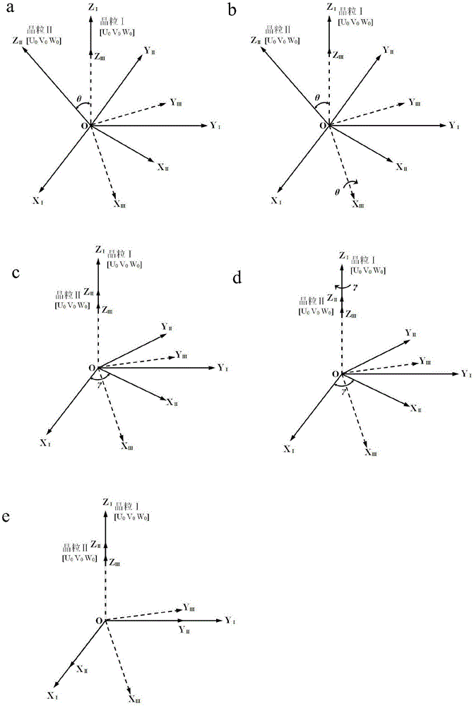
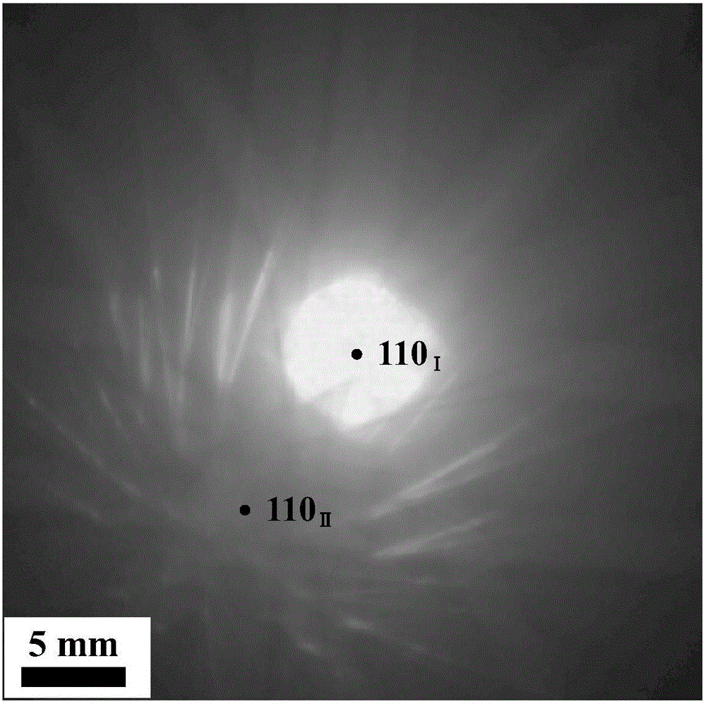
[0067] Step 1: Tilt the grain coordinate system Ⅰ (hereinafter referred to as grain Ⅰ) to the low-index zone axis by using the double-tilt technique. Since the grain is relatively close to the [110] zone axis, the grain Ⅰ is tilted to [110] Zonal axis. When the camera constant is adjusted to 250mm, the grain I Kikuchi line is photographed.

[0068] Step 2: keep the camera constant, and collect the Kikuchi line of grain coordinate system II (hereinafter referred to as grain II).

[0...

Embodiment 2

[0074] The detection material is hot-pressed sintered 5083Al, with an average grain size of 200nm. Cut out a thin slice of 3 mm×5 mm×0.5 mm, and grind it with water sandpaper to a thickness of 30 μm. The Φ3mm sample was cut and double-jet thinned to prepare a thin area.

[0075] The above-prepared sample was clamped on the electron microscope by using the double-tilt sample rod of the Jem2010 electron microscope, and the applied voltage was 200KV. Find the two grains to be detected in the sample.

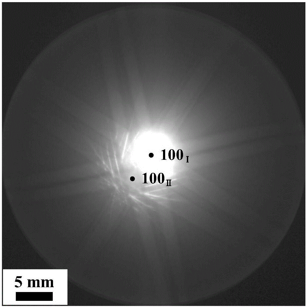
[0076] Step 1: Tilt the crystal grain I to the low-index zone axis by using the double-tilt technique. Since the grain is relatively close to the [001] zone axis, tilt the crystal grain I to the [001] zone axis. When the camera constant is adjusted to 250mm, the grain I Kikuchi line is photographed.

[0077] Step 2: keep the camera constant, and collect the Kikuchi line of grain II.

[0078] Step 3: Use Gatan DigitalMicrograph software to superimpose the collected Kikuchi line o...

Embodiment 3

[0083] The detection material is hot-pressed sintered 5083Al, with an average grain size of 100nm. Cut out a thin slice of 3 mm×5 mm×0.5 mm, and grind it with water sandpaper to a thickness of 30 μm. The Φ3mm sample was cut and double-jet thinned to prepare a thin area.

[0084] The above-prepared sample was clamped on the electron microscope by using the double-tilt sample rod of the Jem2010 electron microscope, and the applied voltage was 200KV. Find the two grains to be detected in the sample.

[0085] Step 1: Direct observation finds that grain I is near the low-index zone axis [110], and when the camera constant is adjusted to 250mm, directly photograph the Kikuchi line of grain I.

[0086] Step 2: keep the camera constant, and collect the Kikuchi line of grain II.

[0087] Step 3: Use Gatan DigitalMicrograph software to superimpose the collected Kikuchi line of grain Ⅰ and Kikuchi line of grain Ⅱ, and pay attention to keep the coincidence of the transmission spots, su...


PUM

PropertyMeasurementUnit
particle sizeaaaaaaaaaa

Abstract

The invention discloses a method for rapidly and accurately measuring low angle grain boundary orientation under a transmission electron microscope. The method comprises the following steps: using a transmission electron microscope double bar-tilting rotation tilting sample, enabling a zone axis of a crystalline grain I in a coordinate system I to be at the position of a positive zone axis, and collecting a convergent beam electron diffraction pattern of the crystalline grain I at the moment; keeping a camera constant L of the transmission electron microscope and the parameter of the convergent beam diffraction condition unchanged, and collecting a convergent beam electron diffraction pattern of a crystalline grain II in a coordinate system II; superposing a kikuchi pattern of the collected crystalline grain I and a kikuchi pattern of the collected crystalline grain II by using software; measuring the distance S between a kikuchi pole of the crystalline grain I and a kikuchi pole of the crystalline grain II as well as the rotation angle gama of the kikuchi pole of the crystalline grain II vertical to the pattern surface relatively to the kikuchi pole of the crystalline grain I; calculating the angle theta according to the geometric characteristic of the kikuchi line, theta=arctan(s/L)=s/L; using a formula (6) cos theta=(cosgama+cosgamacostheta+costheta-1)/2 to calculate the orientation of the crystalline grain I and the crystalline grain II. The method does not need the additional installation of hardware and software, and the common transmission electron microscope is used to measure the orientation.

Description

technical field [0001] The invention relates to the field of microscopic analysis of materials, in particular to a method for quickly and accurately measuring the misorientation of small-angle grain boundaries under a transmission electron microscope. Background technique [0002] Transmission electron microscopy is an important means of material science research: it can not only obtain microscopic images of materials; at the same time, it can detect the composition information of samples; through high-resolution imaging technology, it can also directly observe the atomic arrangement of crystal materials; it can also calibrate phases through diffraction . Therefore, measuring the misorientation between grains under a transmission electron microscope, combined with the above analysis methods, can better characterize and analyze the microstructure of the material, especially the grain boundary structure. [0003] In polycrystalline materials, grain boundaries have a very impo...

Claims


Application Information

Patent Timeline
Patent Type & Authority Applications(China)
IPC IPC(8): G01N23/20
CPCG01N23/20
Inventor 闫志刚林耀军
Owner YANSHAN UNIV
Why Eureka
Try Eureka