

Fertilizer applicator and fertilizer suitable for being used by fertilizer applicator
A fertilizer applicator and fertilizer technology, applied in the application, root water supply, gardening and other directions, can solve the problems of plant damage, fertilizer waste, easy to cause fertilizer damage and so on
- Summary
- Abstract
- Description
- Claims
- Application Information
AI Technical Summary
Problems solved by technology
Method used
Image

Examples
Embodiment 1
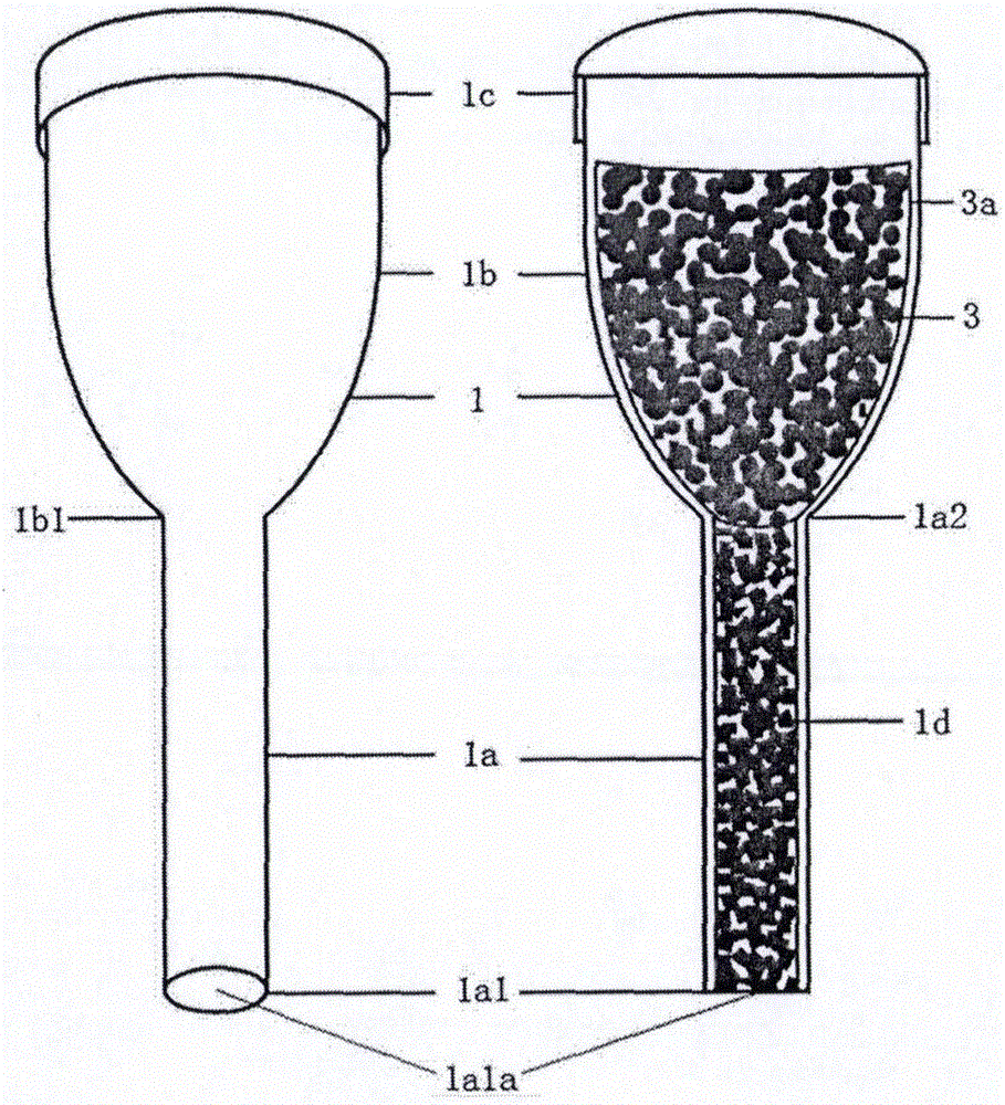
[0108] A fertilizer applicator that can be inserted or completely buried in the soil, see the appearance and internal structure diagram figure 1The fertilizer water guide pipe 1a, the fertilizer cavity 1b, and the cover 1c of the fertilizer applicator 1 are made of plastic; the water-absorbable and water-guiding material 1d in the fertilizer water guide pipe 1a is the coconut palm made of wrapping coconut chaff with non-woven fabric Bran bar; Fertilizer 1 fertilizer water diversion pipe 1a internal diameter is about 1 centimeter, and length is about 3 centimeters; Fertilizer chamber 1 b inner diameter is about 3 centimeters, and length is about 4 centimeters; When this fertilizer applicator 1 is used, add external durable Rotten and permeable cloth 3a wrapped fertilizer 3, then cover the lid 1c, the fertilizer applicator 1 can be inserted from the lower end of the fertilizer water diversion pipe 1a or buried in the soil upright for use, because the fertilizer applicator is over...
Embodiment 2
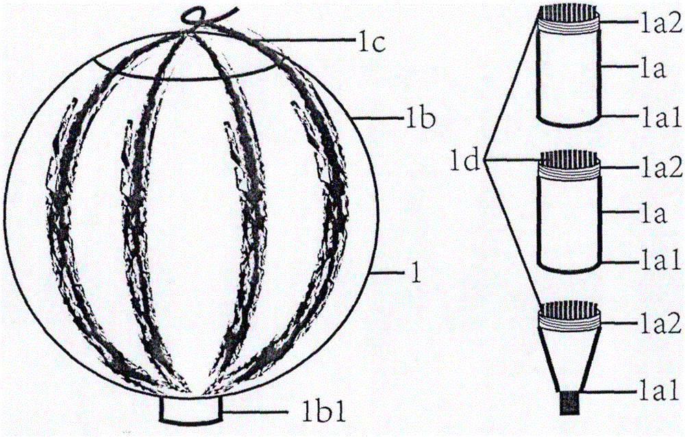
[0110] A kind of fertilizer water diversion pipe with the appearance of watermelon in the fertilizer cavity is a detachable multi-stage fertilizer applicator, the appearance structure diagram and the diagram of each sub-component, see figure 2 The fertilizer water diversion pipe 1a, the fertilizer cavity 1b, and the cover 1c of the fertilizer applicator 1 are made of plastic; the fertilizer applicator 1 fertilizer water diversion pipe 1a is a detachable three-section type, except the tip 1a1 of the lowermost section taper, each section The ports 1a1 and 1a2 of the fertilizer and water diversion pipe 1a are threaded to be connected to each other, and the base part 1b1 of the fertilizer cavity 1b also has threads connected to the upper end 1a2 of the fertilizer and water diversion pipe 1a; the three sections of the fertilizer and water diversion pipe 1a are equipped with useful chemical fibers The water guide rod 1d made, the water guide rod 1d inside it after the three sections...
Embodiment 3
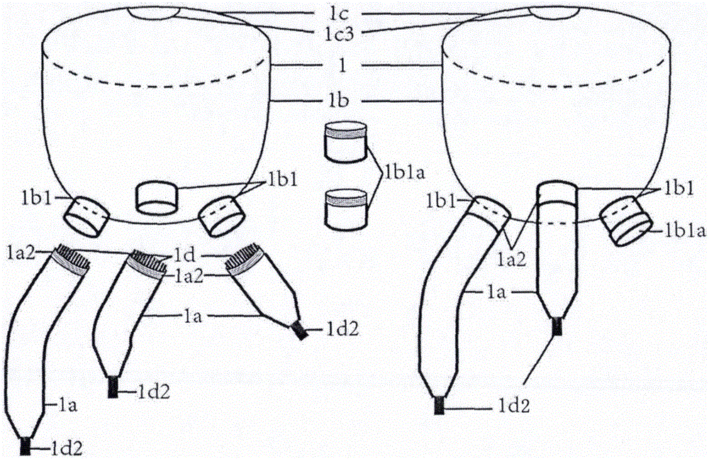
[0112] A fertilizer applicator with detachable multi-claw type fertilizer and water diversion pipe, and multi-claw can be selectively installed. The appearance and structure diagram is shown in image 3 The fertilizer water diversion pipe 1a of the fertilizer applicator 1, the fertilizer chamber 1b, the plug 1b1a of the fertilizer chamber base 1b1, and the cover 1c are made of plastic; the fertilizer water diversion pipe 1a of the 3 branches is equipped with water-conducting materials of chemical fibers 1d2; the fertilizer and water diversion pipe 1a is a detachable three-claw one-piece type, with an inner diameter of about 1 cm, and the three fertilizer and water diversion pipes 1a have different lengths, which are 20 centimeters, 10 centimeters, and 5 centimeters; in this embodiment, the fertilizer applicator 1 Choose to use only two claws (fertilizer water diversion pipe 1a), and the unused claws are blocked at the base of the fertilizer chamber 1b1 with a plug 1b1a; this ki...
PUM
| Property | Measurement | Unit |
|---|---|---|
| Length | aaaaa | aaaaa |
| Length | aaaaa | aaaaa |
Abstract
Description
Claims
Application Information