System and method for preparing patterned metal thin layer through pulse laser-induced forward transfer

A metal thin layer, pulsed laser technology, applied in laser welding equipment, metal processing equipment, optics, etc., can solve the problems of material blockage, difficulty, affecting the use effect, etc., achieve large-scale pattern transfer, reduce manufacturing costs and manufacturing effect of cycle

Active Publication Date: 2017-06-13
BEIJING INSTITUTE OF GRAPHIC COMMUNICATION
View PDF10 Cites 25 Cited by
  • Summary
  • Abstract
  • Description
  • Claims
  • Application Information

AI Technical Summary

Problems solved by technology

[0003] However, due to the limitation of the diameter of the nozzle hole, it is still very difficult to achieve submicron or even smaller precision for functional mate...

Method used


Image

  • System and method for preparing patterned metal thin layer through pulse laser-induced forward transfer
  • System and method for preparing patterned metal thin layer through pulse laser-induced forward transfer
  • System and method for preparing patterned metal thin layer through pulse laser-induced forward transfer

Examples


Embodiment 1

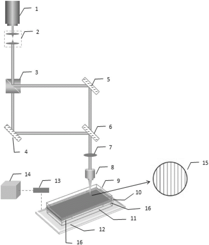
[0056] Such as figure 1 Shown is a schematic diagram of the system structure of the pulsed laser-induced forward transfer patterned metal thin layer of the present invention, wherein, 1 is a pulsed laser, 2 is a collimating beam expander lens group, 3 is a beam splitting prism, 4 and 5 are reflective mirror, 6 is a beam combining mirror, 7 is a focusing lens, 8 is an objective lens, 9 is a transparent initial substrate, 10 is a thin metal layer, 11 is a receiving substrate, 12 is a motorized platform, 13 is a motion controller, 14 is Computer, 15 is an interference pattern, 16 is a spacer, wherein the collimating beam expanding lens group 2 is fixedly connected with the pulse laser 1, the collimating beam expanding lens group 2, the beam splitting prism 3, reflecting mirrors 4 and 5, and the beam combining mirror 6. The focusing lens 7 and the objective lens 8 form an optical path adjustment system. The mirrors 4 and 5 and the beam combiner 6 are respectively fixed on the prec...

Embodiment 2

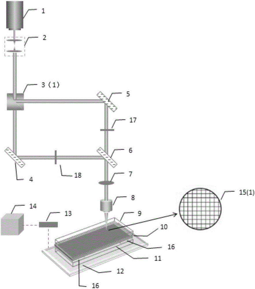
[0075] Such as figure 2 As shown, it is a schematic diagram of the system structure of the pulsed laser-induced forward transfer patterned metal thin layer in this embodiment, wherein, 1 is a pulsed laser, 2 is a collimating beam expander lens group, 3a is a polarization beam splitter prism, 4 and 5 are Mirror, 6 is the beam combining mirror, 7 is the focusing lens, 8 is the objective lens, 9 is the original substrate, 10 is the thin metal layer, 11 is the receiving substrate, 12 is the electric platform, 13 is the motion controller, 14 is the computer , 15 (1) is an interference pattern, 16 is a spacer, 17 is a diffraction grating (also can be an SLM), and 18 is a diffraction grating (also can be an SLM), wherein the collimating beam expander lens group 2 is fixedly connected with the pulse laser 1 Together, the optical path adjustment system includes collimating beam expander lens group 2, polarization beam splitter prism 3a, mirrors 4 and 5, beam combining mirror 6, focusi...


PUM

PropertyMeasurementUnit
Wavelengthaaaaaaaaaa
Pulse widthaaaaaaaaaa
Focal lengthaaaaaaaaaa

Abstract

The invention discloses a system and method for preparing a patterned metal thin layer through pulse laser-induced forward transfer, and belongs to the technical field of laser application and printing electronics. The system comprises a laser light source, a light path adjusting system and a two-dimensional precise motion system, wherein the laser light source is connected with the light path adjusting system; the two-dimensional precise motion system is located below the light path adjusting system; the laser light source is a pulse laser device; the light path adjusting system comprises a collimating beam expander lens assembly and a light splitting element connected with the collimating beam expander lens assembly; the light splitting element is connected with two reflectors at 90 degrees separately; the two reflectors are connected with a beam combiner separately; the beam combiner is connected with an objective lens through a focusing lens; the two-dimensional precise motion system comprises an electric platform, a motion controller and a computer; the computer is connected with an electric platform through the motion controller; and the electric platform is used for putting an initial substrate and a receiving substrate. Fast, high-precision and large-format pattern transfer can be achieved, the manufacturing cost is greatly reduced and the manufacturing cycle is greatly shortened.

Description

technical field [0001] The invention relates to a system and method for making fine patterns of thin metal layers, in particular to a system and method for preparing patterned thin metal layers by pulsed laser-induced forward transfer, which is pre-prepared by pulsed laser-induced forward transfer The metal thin layer is used to transfer the metal thin layer part from the original substrate to the receiving substrate, so as to realize the refined pattern of the submicron structure, and belongs to the field of laser application and printed electronic technology. Background technique [0002] At present, in the field of precision printing, the LIGA process (ie, photolithography, electroforming and embossing) and inkjet printing technology are mainly used to prepare patterned functional devices. For the former, it is necessary to use a mask to prepare micro-nano-scale fine structures. At the same time, the surface structure of the mask will decrease as the number of imprints in...

Claims


Application Information

Patent Timeline
IPC IPC(8): B23K26/06B23K26/08B23K26/362G02B27/09G02B27/10G02B27/12G02B27/28
CPCB23K26/0643B23K26/08B23K26/361G02B27/0955G02B27/10G02B27/126G02B27/283
Inventor 李修李路海徐艳芳郭紫楠
Owner BEIJING INSTITUTE OF GRAPHIC COMMUNICATION
Why Eureka
Try Eureka