
Water purifying device for air conditioning test water system

A technology for water purification and air conditioning testing, applied in water/sewage treatment, water/sludge/sewage treatment, chemical instruments and methods, etc., can solve the problems of repeated or even long-term use, high purchase and maintenance costs, and high working noise problem, to achieve the effect of highlighting the reusability, the convenience of cleaning, and the reasonable and concise structure

Inactive Publication Date: 2017-06-13
HEFEI GENERAL MACHINERY RES INST +1
View PDF7 Cites 4 Cited by
  • Summary
  • Abstract
  • Description
  • Claims
  • Application Information

AI Technical Summary

Problems solved by technology

The use of chemicals, such as scale inhibitors and dispersants, can certainly achieve effective scale inhibition and purification purposes, but the disadvantage is that chemicals such as scale inhibitors and dispersants are corrosive to metals, which is obviously not conducive to repeated or even long-term use.
The use of ionization to purify air conditioner water has the advantages of removing calcium and magnesium and reducing the hardness of water, and is suitable for industrial use; but the disadvantage is that it is easy to increase the sodium content in water, and it is easy to produce acidic water, and it is also harmful to many organic , inorganic compounds, bacteria, viruses have no effect
The ultrasonic purification method has high efficiency and good water purification effect, but it is relatively high in purchase and maintenance costs, and the working noise is high, which will obviously have a certain impact on the working environment of the staff

Method used


Image

  • Water purifying device for air conditioning test water system
  • Water purifying device for air conditioning test water system

Examples


Embodiment Construction

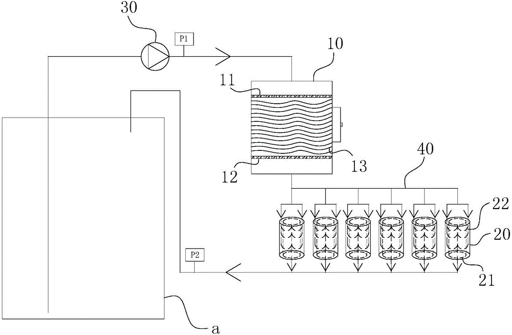
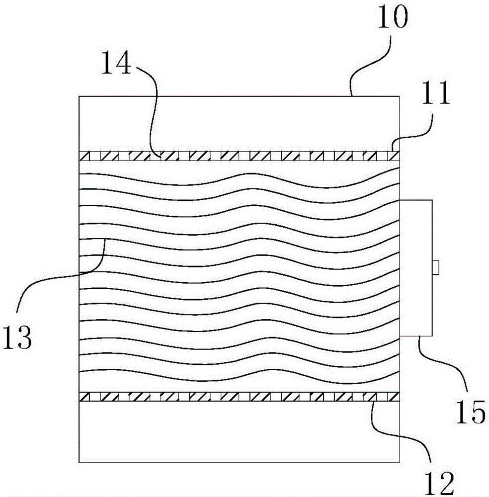
[0022] For ease of understanding, combined here Figure 1-2 , the concrete structure and working mode of the present invention are further described as follows:

[0023] The specific structure of the present invention is as Figure 1-2 As shown, its overall structure includes a water tank a and a circulation pipeline 40 connecting the liquid inlet and the liquid outlet of the water tank a. The circulation pipeline 40 is powered by the water pump 30 , thereby driving the water in the water tank a to form a circulation channel in the circulation pipeline 40 . The size of the water pump 30 is determined according to the size of the whole filter system, and can be designed to handle 5 cubic meters of water per hour when the length and width of the coarse filter box 10 is 500 mm * 500 mm. The coarse filter box 10 and the fine filter box 20 are sequentially arranged on the circulation pipeline 40 along the direction of the circulation channel. in:

[0024] like figure 2 As sho...


PUM

PropertyMeasurementUnit
pore sizeaaaaaaaaaa

Abstract

The invention belongs to the field of air conditioning sewage purification and in particular relates to a water purifying device for an air conditioning test water system. The device comprises a water tank and a secondary filter assembly composed of a coarse filter tank and a refined filter tank; a coarse filter water inlet hole and a coarse filter water outlet hole are separately formed in opposite ends of the coarse filter tank, and a coarse filter core formed by an upper flow equalizing plate, a PU foam body and a lower flow equalizing plate is arranged in an overflowing channel formed by an inner cavity of the coarse filter tank between the coarse filter water inlet hole and the coarse filter water outlet hole; a refined filter water inlet hole and a refined filter water outlet hole are separately formed in opposite two ends of the refined filter tank; a mandrel is arranged in the inner cavity of the refined filter tank and the axis of the mandrel is parallel to a water flow forwarding direction of the refined filter tank; the refined filter tank also comprises a PP foam barrel which sleeves the mandrel. The water purifying device provided by the invention has the advantages of being compact and concise in structure and low in using cost, and can remarkably enhance the water purifying efficiency and effect.

Description

technical field [0001] The invention belongs to the field of purification of air-conditioning sewage, and in particular relates to a water quality purification device for an air-conditioning test water system. Background technique [0002] In the water system used for air conditioning testing, there are a large number of water pipes; these water pipes are used to connect the water tank and other water-using devices, such as condensers or evaporators, which are essential components. In actual use, most of the above-mentioned water pipes use stainless steel or galvanized pipes, which makes oxygen ions or chloride ions cause corrosion of galvanized pipes or stainless steel welds or even pipe walls during the working process of the water system, thereby Form rust foam or rust block and pollute water quality. At present, the general measures to deal with the above problems in the industry mostly use chemical drugs, electric ions or ultrasonic waves. The use of chemicals, such a...

Claims


Application Information

Patent Timeline
Patent Type & Authority Applications(China)
IPC IPC(8): C02F1/00B01D24/10
Inventor 昝世超高启明商允恒张伟黄静张欢王晓光
Owner HEFEI GENERAL MACHINERY RES INST
Learn More