
High-frequency induction evaporation source device

A high-frequency induction, evaporation source technology, used in vacuum evaporation plating, ion implantation plating, metal material coating processes, etc., can solve the problems of uneven heating rate, cracking of evaporation materials, difficult heating of evaporation materials, etc. Avoids the effect of uneven heating rates

Inactive Publication Date: 2017-06-13
WUHAN CHINA STAR OPTOELECTRONICS TECH CO LTD
View PDF5 Cites 11 Cited by
  • Summary
  • Abstract
  • Description
  • Claims
  • Application Information

AI Technical Summary

Problems solved by technology

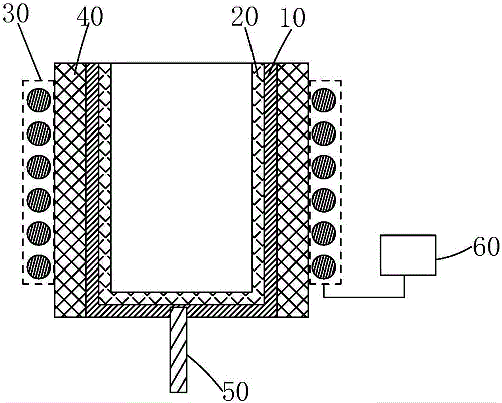
[0006] 1. The evaporating material located far away from the wall of the inner crucible 20 is difficult to be fully heated, resulting in uneven local heating rates;
[0007] 2. The evaporating material located near the wall of the inner crucible 20 will be cracked due to overheating

Method used


Image

  • High-frequency induction evaporation source device
  • High-frequency induction evaporation source device
  • High-frequency induction evaporation source device

Examples


Embodiment Construction

[0032] In order to further illustrate the technical means adopted by the present invention and its effects, the following describes in detail in conjunction with preferred embodiments of the present invention and accompanying drawings.

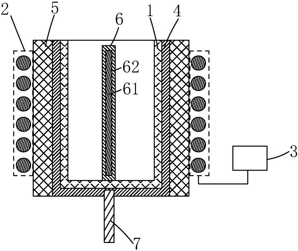
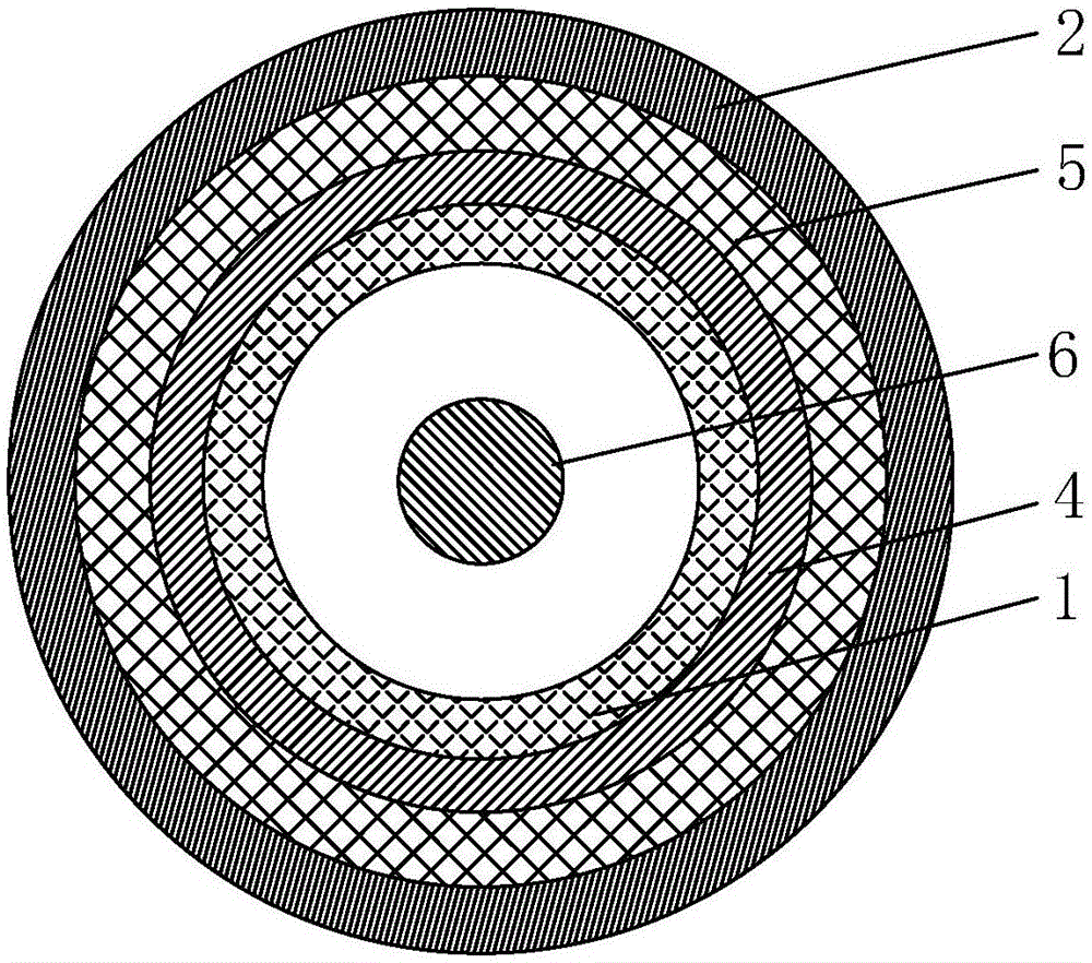
[0033] see figure 2 , the present invention provides a high-frequency induction evaporation source device, including an inner crucible 1 for carrying evaporation materials, an induction coil 2 sleeved on the periphery of the inner crucible 1, a radio frequency generator 3 connected to the induction coil 2, and A radio frequency induction heating component (High Frequency Induced Heater) 6 arranged in the inner crucible 1;

[0034] The induction coil 2 is used to receive the alternating current emitted by the radio frequency generator 3 to generate an induced magnetic field; An induced current is generated in the induced magnetic field and heat is generated, thereby heating the evaporation material.

[0035] The high-frequency induction evap...


PUM


Abstract

The invention provides a high-frequency induction evaporation source device. The high-frequency induction evaporation source device comprises an inner crucible used for bearing evaporation materials, an induction coil arranged on the periphery of the inner crucible in a sleeving mode, a radio frequency generator connected with the induction coil and a radio frequency induction heating component arranged in the inner crucible. The induction coil is used for receiving alternating current emitted by the radio frequency generator to generate an induced magnetic field. The radio frequency induction heating component comprises an induction kernel body with the electrical conductivity. The induction kernel body generates induced current in the induction magnetic field of the induction coil and generates heat to heat the evaporation materials. Compared with an existing high-frequency induction evaporation source device, the high-frequency induction evaporation source device has the advantages that the heating area of the evaporation materials in the inner crucible can be effectively dispersed, and accordingly, the problems that the local heating rate of evaporation materials is not uniform and evaporation materials close to the wall of the inner crucible are locally overheated and crack are effectively avoided.

Description

technical field [0001] The invention relates to the field of display technology, in particular to a high-frequency induction evaporation source device. Background technique [0002] OLED (Organic Light-Emitting Diode, organic light-emitting diode) display, also known as organic electroluminescence display, is a new flat panel display device, because of its simple preparation process, low cost, low power consumption, high luminous brightness, Wide range of working temperature, light and thin size, fast response speed, easy to realize color display and large-screen display, easy to realize matching with integrated circuit driver, easy to realize flexible display, etc., so it has broad application prospects. At present, the mass-produced OLED manufacturing technology adopts the method of vacuum evaporation to prepare OLED material thin films. [0003] The vacuum evaporation method is to heat the raw material to be formed in the evaporation container in a vacuum chamber, so tha...

Claims


Application Information

Patent Timeline
Patent Type & Authority Applications(China)
IPC IPC(8): C23C14/26
CPCC23C14/26C23C14/243
Inventor 沐俊应
Owner WUHAN CHINA STAR OPTOELECTRONICS TECH CO LTD
Learn More