Preparation method of frequency-reconfigurable sleeve-dipole antennas based on GaAs (gallium arsenide)

A technology of dipole antenna and sleeve, which is applied in the field of preparation of frequency reconfigurable sleeve dipole antenna, can solve problems such as difficult to meet various system requirements and application environments, and achieve small size, easy processing, and low profile Effect

Active Publication Date: 2017-06-13
XIAN CREATION KEJI CO LTD
View PDF5 Cites 0 Cited by
  • Summary
  • Abstract
  • Description
  • Claims
  • Application Information

AI Technical Summary

Problems solved by technology

At the same time, in order to break through the fixed performance of traditional antennas that are difficult to meet diverse system requirements and complex and changeable application environments, the concept of reconfigurable antennas has been valued and developed.

Method used


Image

  • Preparation method of frequency-reconfigurable sleeve-dipole antennas based on GaAs (gallium arsenide)
  • Preparation method of frequency-reconfigurable sleeve-dipole antennas based on GaAs (gallium arsenide)
  • Preparation method of frequency-reconfigurable sleeve-dipole antennas based on GaAs (gallium arsenide)

Examples


Embodiment 1

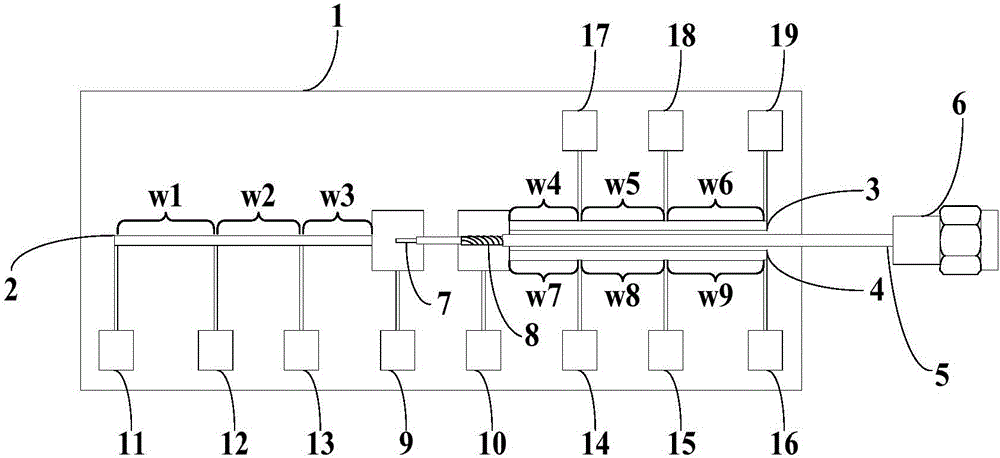
[0056] See figure 1 , figure 1 A schematic structural diagram of a GaAs-based frequency reconfigurable sleeve dipole antenna provided by an embodiment of the present invention. The antenna includes a GaAs substrate material 1, an SPiN diode antenna arm 2, a first SPiN diode sleeve 3, a second SPiN diode sleeve 4, a coaxial feeder 5, a DC bias line 9, 10, 11, 12, 13, 14, 15, 16, 17, 18, 19; among them,

[0057]The SPiN diode antenna arm 2, the first SPiN diode sleeve 3, the second SPiN diode sleeve 4, and the DC bias lines 9, 10, 11, 12, 13, 14, 15, 16, 17, 18, and 19 are all fabricated on the GaAs substrate material 1; the SPiN diode antenna arm 2, the first SPiN diode sleeve 3 and the second SPiN diode sleeve 4 pass through the coaxial feeder 5 connection, the inner core wire 7 of the coaxial feeder 5 is connected to the SPiN diode antenna arm 2 and the outer conductor 8 of the coaxial feeder 5 is connected to the first SPiN diode sleeve 3 and the second SPiN diode sleeve...

Embodiment 2

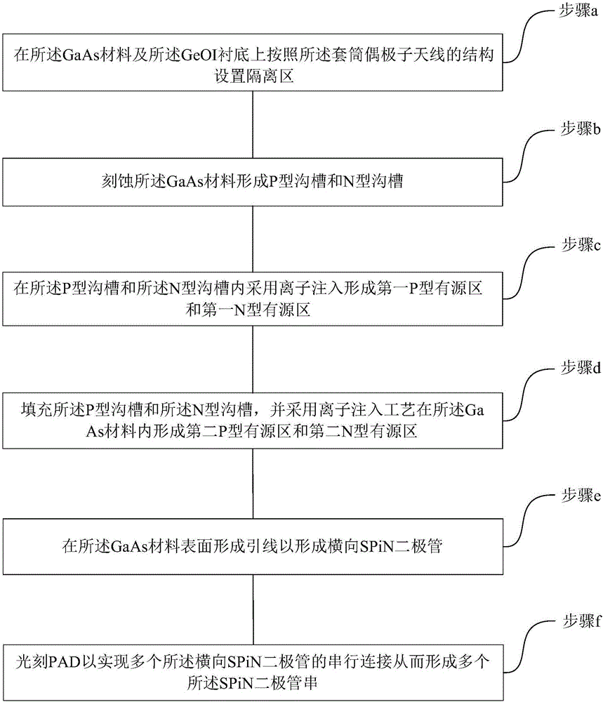
[0079] See image 3 , image 3 A schematic diagram of a method for preparing an SPiN diode string provided by an embodiment of the present invention. The preparation method may comprise the steps of:

[0080] (a) setting an isolation region on the GaAs material and the GeOI substrate according to the structure of the sleeve dipole antenna;

[0081] (b) etching the GaAs material to form a P-type trench and an N-type trench;

[0082] (c) forming a first P-type active region and a first N-type active region by ion implantation in the P-type trench and the N-type trench;

[0083] (d) filling the P-type trench and the N-type trench, and forming a second P-type active region and a second N-type active region in the GaAs material by ion implantation;

[0084] (e) forming leads on the surface of the GaAs material to form a lateral SPiN diode;

[0085] (f) Photoetching the PAD to realize serial connection of a plurality of lateral SPiN diodes to form a plurality of SPiN diode stri...

Embodiment 3

[0108] See Figure 6a-Figure 6s , Figure 6a-Figure 6s It is a schematic diagram of a method for fabricating a lateral SPiN diode according to an embodiment of the present invention. In this embodiment, on the basis of the above-mentioned embodiments, the preparation of the SPiN diode is described in detail by taking the preparation of a GaAs-based SPiN diode (solid-state plasma PiN diode) with a plasma region length of 100 μm as an example, and the specific steps are as follows:

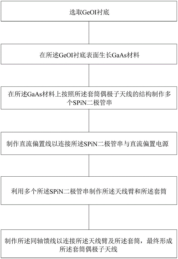
[0109] Step 1, substrate material preparation steps:

[0110] (1a) if Figure 6a As shown, a GeOI substrate 101 with (100) crystal orientation is selected, and a GaAs layer 102 is deposited on the top layer Ge by MOCVD method, the doping type is p-type, and the doping concentration is 10 14 cm -3 , the thickness of the top GaAs layer is 50 μm;

[0111] (1b) if Figure 6b As shown, the method of chemical vapor deposition (Chemical vapor deposition, referred to as CVD) is used to deposit a layer...


PUM


Abstract

The invention relates to a preparation method of frequency-reconfigurable sleeve-dipole antennas based on GaAs (gallium arsenide). The preparation method includes the steps: selecting GeOI (germanium on insulator) substrates; growing GaAs materials on the surfaces of the GeOI substrates; manufacturing a plurality of SPiN diode strings on the GaAs materials according to structures of the sleeve-dipole antenna; manufacturing direct-current offset lines to connect with SPiN diode strings and a direct-current offset power supply; manufacturing antenna arms and sleeves by the aid of the SPiN diode strings; manufacturing coaxial feed lines to connect with the antenna arms and the sleeves to form the sleeve-dipole antennas. According to the sleeve-dipole antennas, conduction of SPiN diodes is controlled by the metal direct-current offset lines, so that the plasma antenna arms and the lengths of the sleeves can be adjusted, the working frequency of the antennas can be reconfigured, and the sleeve-dipole antennas have the advantages that the antennas are easy to integrate and invisible, and the frequency can rapidly jump.

Description

technical field [0001] The invention belongs to the technical field of semiconductors, and in particular relates to a preparation method of a GaAs-based frequency reconfigurable sleeve dipole antenna. Background technique [0002] Today, with the rapid development of antenna technology, the traditional sleeve monopole antenna is widely used in vehicle, shipboard and remote sensing due to its wide frequency band, high gain, simple structure, easy feeding, longitudinal size, omnidirectional and many other advantages. and other communication systems. However, the electrical characteristics of the commonly used sleeve monopole antenna not only depend on the sleeve structure, but also have a great relationship with the ground, which makes it difficult to meet the requirements of broadband and miniaturization for elevated antennas in shipboard communication engineering . [0003] The sleeve dipole antenna is a dipole antenna formed by adding a coaxial metal sleeve to the antenna...

Claims


Application Information

Patent Timeline
Patent Type & Authority Applications(China)
IPC IPC(8): H01L21/04H01L29/66H01Q1/38H01Q7/00H01Q23/00
CPCH01L21/04H01L29/6609H01Q1/38H01Q7/00H01Q23/00
Inventor 张亮左瑜
Owner XIAN CREATION KEJI CO LTD
Why Eureka
Try Eureka