Energy-saving type VOCs (Volatile Organic Compounds) treatment device based on multi-stage dielectric barrier discharge
A dielectric barrier discharge and treatment device technology, which is applied in the field of plasma, can solve the problems of increased energy consumption and cost for plate cooling, difficulty in the application of flat plate reactors, and inability to process large areas of sleeve reactors. Effect and automation level improvement, high work efficiency, high energy utilization effect
- Summary
- Abstract
- Description
- Claims
- Application Information
AI Technical Summary
Problems solved by technology
Method used
Image
Examples
specific Embodiment approach 1
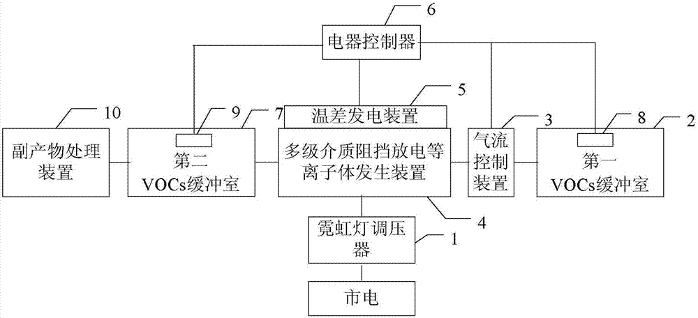
[0036] Specific implementation mode one: combine figure 1 This embodiment is specifically described. The energy-saving VOCs processing device based on multi-stage dielectric barrier discharge described in this embodiment includes a neon sign voltage regulator 1, a first VOCs buffer chamber 2, an airflow control device 3, and a multi-stage dielectric barrier discharge plasma Body generator 4, thermoelectric power generation device 5, electrical controller 6, second VOCs buffer chamber 7, first VOCs concentration sensor 8, second VOCs concentration sensor 9 and by-product treatment device 10;
[0037] The neon sign voltage regulator 1 converts the mains power and provides a high-voltage power supply for the multi-stage dielectric barrier discharge plasma generator 4, the first VOCs buffer chamber 2 is used to hold the VOCs to be treated, and the first VOCs concentration sensor 8 is placed in the first In the VOCs buffer chamber 2, the gas flowing out of the first VOCs buffer cha...
specific Embodiment approach 2
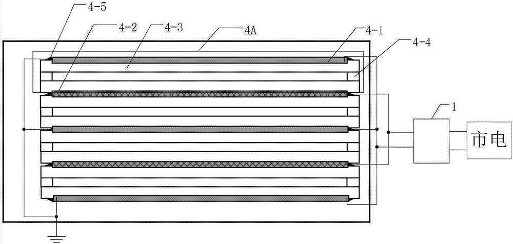
[0039] Specific implementation mode two: combination figure 2 This embodiment is described in detail. This embodiment is a further description of the energy-saving VOCs processing device based on multi-level dielectric barrier discharge described in the first embodiment. In this embodiment, the multi-level dielectric barrier discharge plasma generator 4 includes at least one set of discharge cells 4A;
[0040] Each group of discharge cells includes a rectangular copper plate 4-1, a rectangular copper mesh 4-2, two ceramic dielectric sheets 4-3, gaskets 4-4 and TiO 2 -γAl 2 o 3 catalyst;
[0041] Two ceramic dielectric sheets 4-3 are placed relatively parallel, and a groove is respectively opened on the opposite surface of the two ceramic dielectric sheets 4-3, and a rectangular copper plate 4-1 and a rectangular copper mesh 4-2 are respectively embedded, and the two The opposite surface of the ceramic dielectric sheet 4-3 is a closed space formed by gaskets 4-4 arranged a...
specific Embodiment approach 3
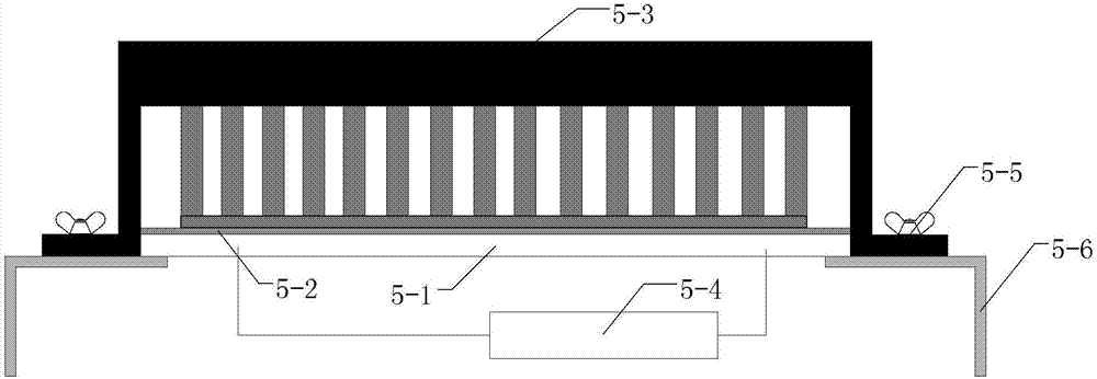
[0051] Specific implementation mode three: combination image 3 This embodiment is described in detail. This embodiment is a further description of the energy-saving VOCs processing device based on multi-stage dielectric barrier discharge described in the second embodiment. In this embodiment, the thermoelectric power generation device 5 includes a thermoelectric power generation sheet 5-1 , thermal conductive silicone grease layer 5-2, radiator 5-3 and boost voltage regulator module 5-4;
[0052] The cold end of the thermoelectric power generation sheet 5-1 is provided with a layer of heat-conducting silicone grease layer 5-2, and a heat sink 5-3 is fixed on the heat-conducting silicon grease layer 5-2, and the hot end of the thermoelectric power generation sheet 5-1 is connected to the rectangular copper plate 4-2. 1 The surface that is not in contact with the ceramic dielectric sheet 4-3 is in close contact, and the voltage output by the thermoelectric generation sheet 5-1 ...
PUM
| Property | Measurement | Unit |
|---|---|---|
| Diameter | aaaaa | aaaaa |
Abstract
Description
Claims
Application Information
 - R&D
- Intellectual Property
- Life Sciences
- Materials
- Tech Scout
- Unparalleled Data Quality
- Higher Quality Content
- 60% Fewer Hallucinations
Browse by: Latest US Patents, China's latest patents, Technical Efficacy Thesaurus, Application Domain, Technology Topic, Popular Technical Reports.
© 2025 PatSnap. All rights reserved.Legal|Privacy policy|Modern Slavery Act Transparency Statement|Sitemap|About US| Contact US: help@patsnap.com


