

Hemispheric finishing grinding wheel for ultra-precision machining
An ultra-precision machining and hemispherical technology, which is applied in the direction of bonded grinding wheels, metal processing equipment, manufacturing tools, etc., can solve the problems that grinding cannot achieve free-form surface finishing, surface roughness is difficult to achieve, and polishing processing efficiency is low. The effect of improving finishing efficiency, practical mechanical structure and low cost of use
- Summary
- Abstract
- Description
- Claims
- Application Information
AI Technical Summary
Problems solved by technology
Method used
Image

Examples
specific Embodiment approach 1
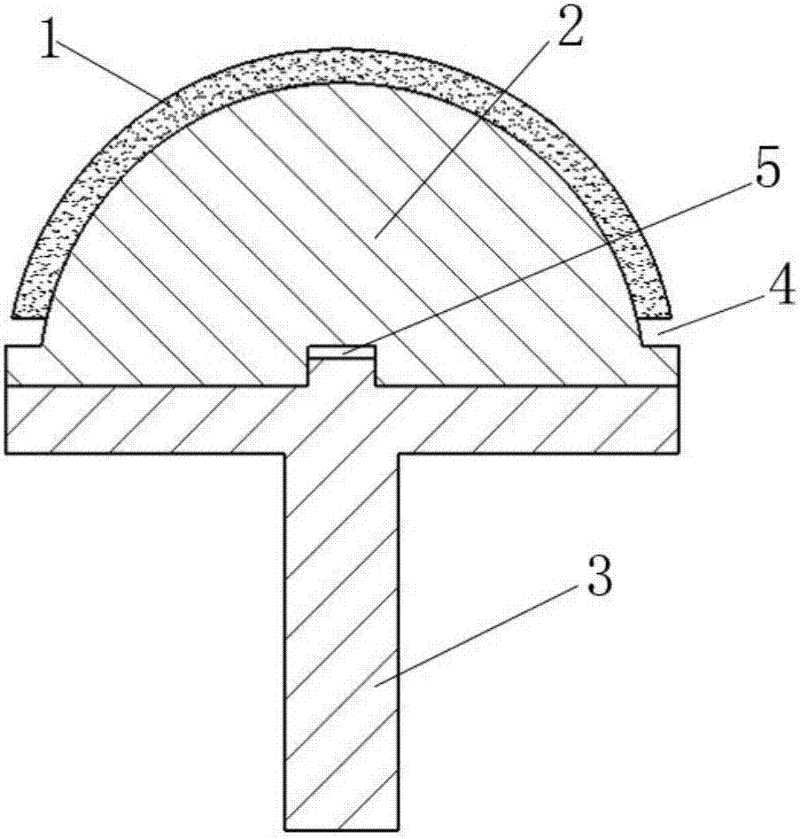
[0018] Embodiment 1: A hemispherical smooth grinding wheel for ultra-precision machining in this embodiment is specifically composed of an abrasive layer 1, a grinding wheel base 2 and a grinding wheel support 3. figure 1 shown;
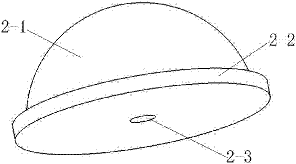
[0019] The grinding wheel matrix 2 is composed of a hemisphere 2-1, a fixed plate 2-2 and a positioning hole 2-3. Figure 3a As shown in and b, the hemisphere 2-1 is arranged on the fixed plate 2-2, and a positioning hole 2-3 with a radius r and a depth smaller than the thickness of the fixed plate is set at the center of the fixed plate 2-2;
[0020] The grinding wheel support 3 is composed of a positioning boss 3-1, a support plate 3-2 and a grinding wheel rod 3-3;
[0021] The positioning boss 3-1 is located at the center of the upper end of the support plate 3-2, the grinding wheel rod 3-3, the positioning boss 3-1 and the support plate 3-2 are coaxial, and the grinding wheel rod 3-3 is used to support the support plate 3 -2 as Figure 4 ;
...
specific Embodiment approach 2
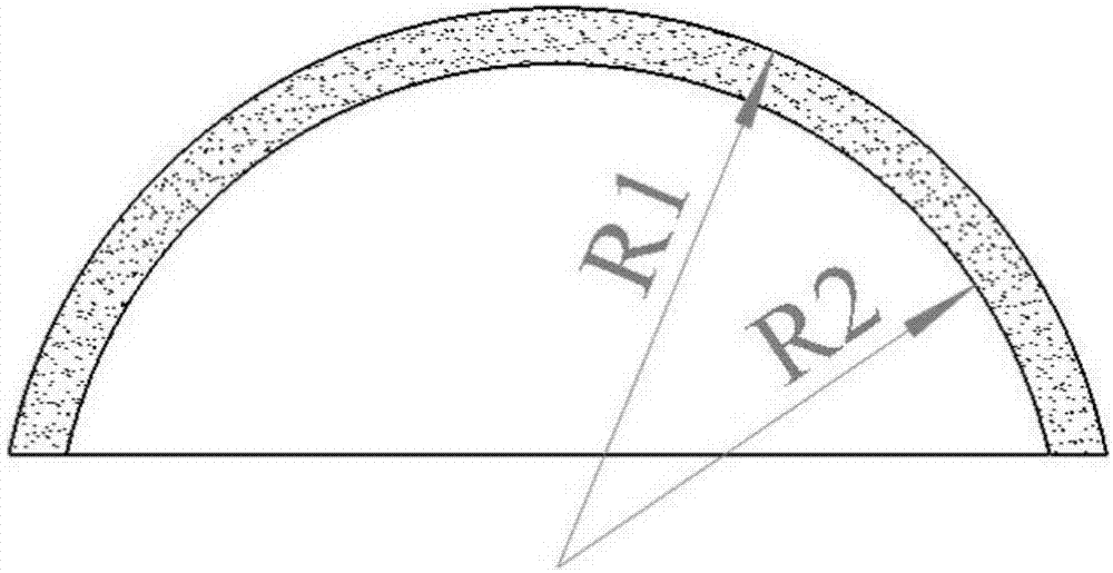
[0025] Embodiment 2: The difference between this embodiment and Embodiment 1 is that the thickness of the abrasive layer 1 ranges from 5 to 10 mm; the abrasive layer 1 is made of abrasive and bonding agent, wherein the abrasive is diamond, cubic nitride One of boron, silicon carbide or corundum, the binder type is one of metal, ceramic or resin. Other steps and parameters are the same as those in Embodiment 1.
specific Embodiment approach 3
[0026] Embodiment 3: The difference between this embodiment and Embodiment 1 or 2 is that the bonding agent used for the bonded abrasive layer 1 and the hemisphere 2-1, and the fixing plate 2-2 are bonded to the support plate 3- 2 The adhesive used and the adhesive used for bonding the fixing plate 2-2 and the support plate 3-2 are high-temperature-resistant adhesives, wherein the high-temperature-resistant adhesive is a high-temperature-resistant epoxy adhesive or a high-temperature-resistant phenolic resin adhesive. Other steps and parameters are the same as those in Embodiment 1 or Embodiment 2.
PUM
| Property | Measurement | Unit |
|---|---|---|
| Thickness value | aaaaa | aaaaa |
| Radius r | aaaaa | aaaaa |
Abstract
Description
Claims
Application Information