Method for realizing carbon dioxide cycle power generation based on waste heat from cement plant

A technology of cycle power generation and carbon dioxide, applied in cement production, waste heat treatment, machine/engine, etc., can solve problems such as inappropriateness, and achieve the effects of reducing pollution, efficient recovery, and extensive energy utilization

Active Publication Date: 2017-06-23
长沙紫宸科技开发有限公司
View PDF6 Cites 6 Cited by
  • Summary
  • Abstract
  • Description
  • Claims
  • Application Information

AI Technical Summary

Problems solved by technology

Obviously, the existing CO 2 Cycle power generation te...

Method used


Image

  • Method for realizing carbon dioxide cycle power generation based on waste heat from cement plant
  • Method for realizing carbon dioxide cycle power generation based on waste heat from cement plant

Examples


Embodiment 1

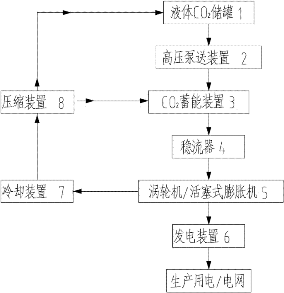
[0040] Such as figure 1 As shown, the present invention provides a method for utilizing the waste heat of a cement plant to realize carbon dioxide cycle power generation, and the CO captured during the production and emission reduction process of the cement plant 2 Stored in liquid CO for liquefaction of working fluid 2 In the storage tank 1, the liquid CO is pumped by the high-pressure pumping device 2 2 Low pressure liquid CO in storage tank 1 2 Fluid continuously pressed into CO 2 In the energy storage device 3;

[0041] CO 2 The energy storage device 3 is a liquefied CO 2 The fluid directly absorbs the waste heat of waste gas or high-temperature thermal energy generated by the cement production line and converts it into high-pressure thermal supercritical CO 2 Fluid device, the device is provided with CO 2 Fluid energy storage mechanism, the mechanism takes CO 2 Fluid is the working medium; CO 2The fluid energy storage mechanism is set on the side wall or the top ...

Embodiment 2

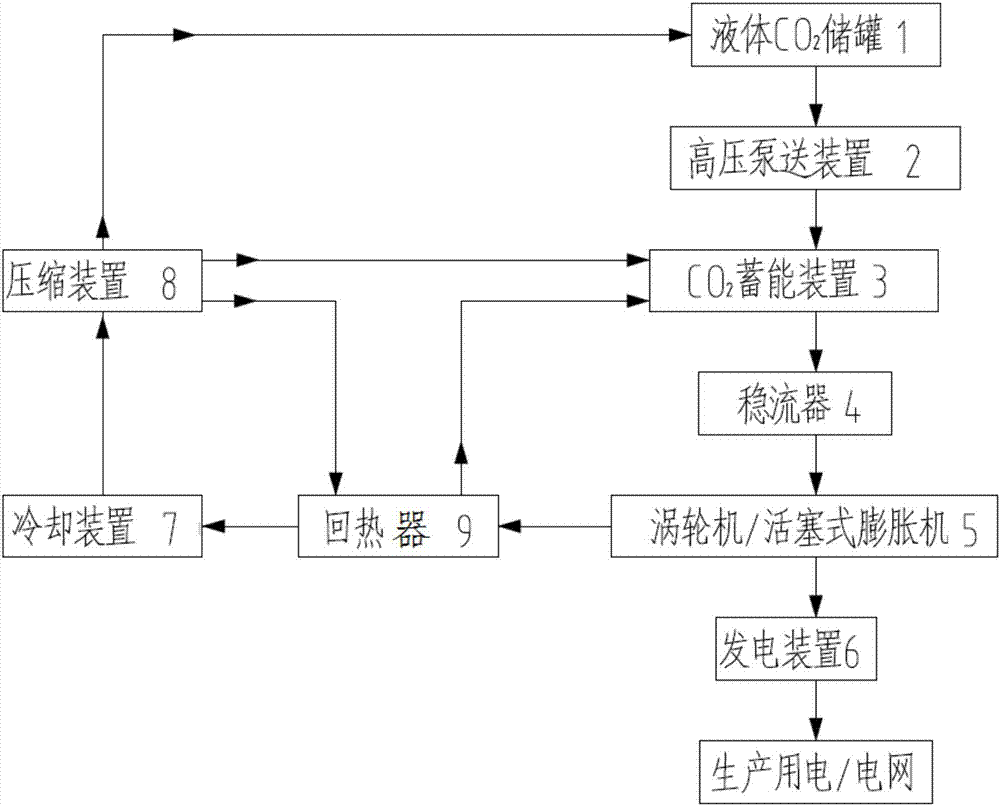
[0045] like figure 2 As shown, the difference from Example 1 is that the method also includes heat recovery, which is manifested as: the low-pressure liquid CO is discharged after the turbine / piston expander 5 performs work and energy release. 2 After the fluid recovers the waste heat through the regenerator 9, the low-pressure liquid CO 2 After the fluid is cooled by the cooling device 7 and compressed by the compression device 8, the compressed fluid is sent into the liquid CO 2 The storage tank 1 is used for circulation; or the low-pressure liquid CO is discharged after the turbine / piston expander 5 releases energy 2 After the waste heat is recovered by the regenerator 9, the fluid is cooled by the cooling device 7 and compressed by the compression device 8, and the compressed fluid enters the recirculator 9 again to absorb the waste heat and then is sent to CO 2 Circulating energy storage power generation in the energy storage device 3;

[0046] Or discharge the low-pr...

Embodiment 3

[0048] The difference from Example 1 is that CO 2 The energy storage device adopts a specific kiln hood with built-in CO 2 Energy storage device and high temperature section of kiln carcass radiate CO 2 energy storage device; both devices are equipped with CO 2 Fluid energy storage mechanism, the mechanism takes CO 2 Fluid is the working medium; CO 2 The fluid energy storage mechanism is respectively arranged on the side wall or roof of the kiln hood and kiln body. Waste heat or radiant heat comes from the kiln hood and kiln body. Specifically, it can be the 100-500 ℃ clinker discharged from the grate cooler for cooling. Waste waste heat, radiant heat and conduction heat at 800°C to 1500°C in the kiln hood, conduction and radiation heat at 300°C to 500°C in the high temperature section of the rotary kiln body, conduction and radiation heat at 150°C to 300°C in the low temperature section of the rotary kiln body; These four different waste heat or radiant heat are replaced ...


PUM


Abstract

The invention provides a method for realizing carbon dioxide cycle power generation based on waste heat from a cement plant. According to the method, CO2 captured during emission reduction is used as a working medium and is cooled and compressed into liquid CO2, the low-pressure liquid CO2 fluid is conveyed into different CO2 energy storage devices through high-pressure pumping devices with the extremely-low energy consumption, various waste heat generated in the cement production process is used as the energy for energy storage of the low-pressure liquid CO2 fluid, and high-pressure thermal supercritical CO2 fluid with the fluctuations and/or different temperatures and different heat densities is generated and is tempered and changed into isothermal-isobaric supercritical CO2 fluid through a steady flow regulator to be stably supplied to a turbine/piston expander so that the turbine/piston expander can do work to drive an electric generator to generate electricity; and carbon dioxide cycle power generation is realized, efficient heat recycling can be achieved, the high heat efficiency is achieved, surplus energy is stored and used effectively, and flexible adjustment and utilization of the energy are achieved.

Description

technical field [0001] The invention relates to the technical field of low-carbon and energy utilization, in particular to a method for utilizing the waste heat of a cement plant to realize carbon dioxide cycle power generation. Background technique [0002] Climate change has become one of the issues affecting human survival and development, and carbon dioxide emitted by industry is considered to be the main cause of climate warming. As the largest developing country in the world, our country uses coal as its primary energy and thermal power as its secondary energy as its energy structure. With the rapid growth of economic aggregate, the CO of primary energy and secondary energy 2 Emissions have the characteristics of fast growth and large total amount, but the current economical CCS or CCUS technology options for carbon emission reduction and climate change are limited, mainly concentrated in coal chemical industry, syngas and coal gasification-gas-steam combined power ge...

Claims


Application Information

Patent Timeline
IPC IPC(8): F01K25/10F27D17/00
CPCF01K25/103F27D17/004Y02P10/25Y02P40/121
Inventor 尹小林
Owner 长沙紫宸科技开发有限公司
Why Eureka
Try Eureka