Driven centrifugal unit and solid-liquid separation equipment comprising same

A technology of centrifugal cover and centrifugal drum, which is applied in the field of centrifuges, and can solve problems such as complex manufacturing process, difficulty in cleaning and verification of centrifugal equipment disassembly and assembly of centrifugal drum, large noise and vibration, etc.

Inactive Publication Date: 2017-06-30
唐凌霄
View PDF0 Cites 0 Cited by
  • Summary
  • Abstract
  • Description
  • Claims
  • Application Information

AI Technical Summary

Problems solved by technology

[0003] At present, the commonly used small centrifuges are all separated and reassembled by driving parts (mainly motors) and solid-liquid separation parts (mainly liquid collection and discharge chambers and centrifugal drums). Centrifugal unit) are all mechanically fixed on the transmission shaft, which makes it difficult to disassemble and assemble the centrifugal drum and the cleaning verification of the centrifugal equipment, and the equipment is too complicated and heavy, the noise and vibration are too large, the manufacturing process is complicated, and the maintenance is inconvenient. However, it cannot fully meet the needs of the complete separation of solid-liquid mixtures in laboratory experiments and pilot experiments.

Method used


Image

  • Driven centrifugal unit and solid-liquid separation equipment comprising same
  • Driven centrifugal unit and solid-liquid separation equipment comprising same
  • Driven centrifugal unit and solid-liquid separation equipment comprising same

Examples


Embodiment 1

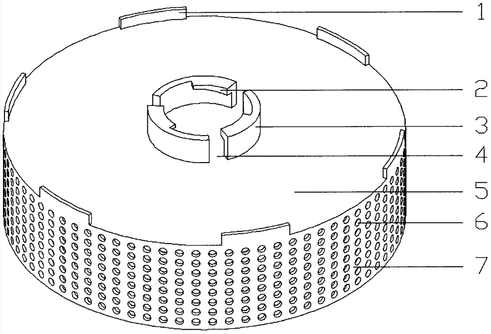
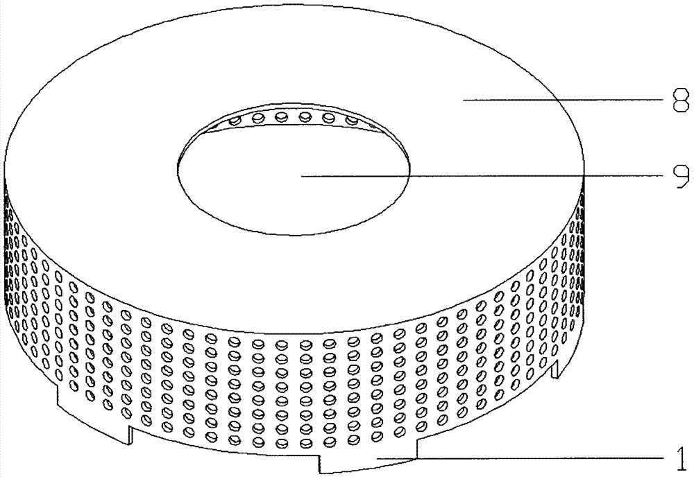
[0185] This embodiment is a driven centrifugal unit with a lock cylinder (3), and its structural schematic diagram is shown in Fig. 1 (comprising Figure 1A and Figure 1B ).

[0186] As shown in Figure 1, according to Figure 8 The method (7) in turn passes through the following steps:

[0187] The first step: select the steel plate;

[0188] Step 2: Stamping and forming the main body with the centrifugal cover (8), feeding hole (9), card-shaped protrusion (1), centrifugal drum (7) and the centrifugal through hole (6) formed by punching on it Part A embryo body (i.e. the first metal part with centrifuge lid and centrifuge bowl);

[0189] The third step: injection molding main part C (driven centrifugal unit);

[0190] The driven centrifugal unit obtained in 3 steps has: a centrifugal cover (8), a feed hole (9), a centrifugal drum (7) and a centrifugal through hole (6) on it, and a centrifuge drum located at the edge of the rear end cover and the centrifugal drum. The lo...

Embodiment 2

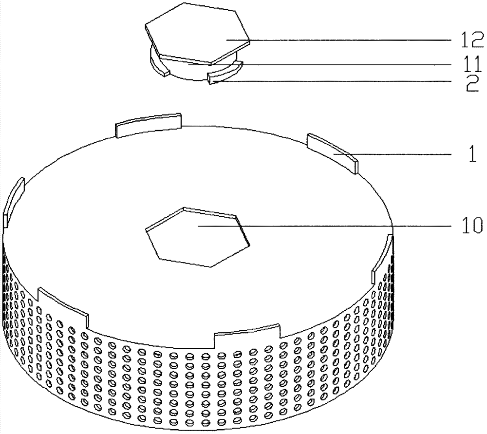
[0192] This embodiment is a driven centrifugal unit with a hexagonal lock hole (10), and its structural schematic diagram is shown in figure 2 .

[0193] Such as figure 2 shown, according to Figure 8 The method (8) in turn passes through the following steps:

[0194] The first step: select the steel plate;

[0195] The second step: stamping and forming the body part B embryo body (that is, having part of the rear end cap and the first metal part of the centrifuge bowl);

[0196] Step 3: Injection molding the main body B of the centrifugal cover precursor;

[0197] Step 4: Process the centrifugal cover precursor through the closing process of the closing machine to form the centrifugal cover and then form it into a driven centrifugal unit;

[0198] The driven centrifugal unit obtained in 4 steps in total has: centrifugal cover, feeding hole, centrifugal drum (7) and the centrifugal through hole (6) on it, locking structure-card located at the junction between the edge ...

Embodiment 3

[0200] This embodiment is a driven centrifugal unit with an independent rear end cover (17), and its structural schematic diagram is shown in Fig. 3 (including Figure 3A and Figure 3B ).

[0201] As shown in Figure 3, according to Figure 7 The method (1) in turn passes through the following steps:

[0202] The first step: select the steel plate;

[0203] The second step: punching the centrifugal through hole;

[0204] The third part: rolling and connecting into a centrifugal drum (that is, the first metal part with a centrifugal drum);

[0205] Step 4: Injection molding the main body A;

[0206] The main part A obtained in 4 steps in total has: the centrifugal cover (8), the feeding hole (9), the centrifugal drum (7) and the centrifugal through hole on it, and the rear end cover locking structure located outside the bottom end of the main part A- The arc-shaped protrusion (2A), the first sealing surface (19) located on the outer edge of the centrifugal cover, and the ...


PUM


Abstract

The invention relates to a driven centrifugal unit and solid-liquid separation equipment comprising the same. The driven centrifugal unit is characterized by comprising a centrifugal cover, a centrifugal rotating barrel, a back end cover and a locking structure and / or a locking unit; and the solid-liquid separation equipment is selected from equipment A (comprising a driving unit, the driven centrifugal unit, a liquid collecting and draining unit, a rotating supporting unit and a stator assembly) and equipment B (comprising a fluid channel, the driven centrifugal unit, a rotating supporting unit and a stator assembly). The driven centrifugal unit and the solid-liquid separation equipment have the beneficial effects as follows: the driven centrifugal unit is simple to manufacture and assemble and is convenient to assemble and disassemble during use, the equipment is easy to maintain, clean and verify, and various defects or faults of existing solid-liquid separation equipment can be overcome.

Description

technical field [0001] The invention relates to a driven centrifugal unit and solid-liquid separation equipment with the driven centrifugal unit. The final product form is a small solid-liquid mixture centrifugal separation equipment, which belongs to the field of centrifuges. Background technique [0002] In the research process of small laboratory test and pilot test, the most commonly used solid-liquid separation equipment is mainly the combination of Buchner funnel and suction filter bottle and centrifuges of various specifications, and the combination of Buchner funnel and suction filter bottle is only suitable for In laboratory research, in order to simulate the actual situation in production and provide necessary centrifuge operation data for production, centrifuges are more recommended. [0003] At present, the commonly used small centrifuges are all separated and reassembled by driving parts (mainly motors) and solid-liquid separation parts (mainly liquid collection...

Claims


Application Information

Patent Timeline
Patent Type & Authority Applications(China)
IPC IPC(8): B04B1/00B04B7/02B04B7/08B04B9/08B29C45/00B29K23/00B29K309/08
CPCB04B1/00B04B7/02B04B7/085B04B9/08B29C45/0001B29K2023/12B29K2309/08B04B2009/085B04B2007/025
Inventor 唐凌霄
Owner 唐凌霄
Why Eureka
Try Eureka