Waste fermentation device using overclocking technology

A fermentation device and waste technology, which is applied in fertilization devices, organic fertilizer equipment, organic fertilizer preparation, etc., can solve the problems of surrounding environmental impact, operator physical damage, and difficulty in collecting and disposing of odor

Inactive Publication Date: 2017-07-04
NANJING BEITE AC EQUIP CO LTD
View PDF14 Cites 1 Cited by
  • Summary
  • Abstract
  • Description
  • Claims
  • Application Information

AI Technical Summary

Problems solved by technology

[0002] Traditional fertilizer reaction devices can be divided into two types: reactor and non-reactor. The common reactors mainly include drum type, tower type, tunnel kiln type, tank type, etc. The non-reactor types include strip stack type and static stack type. etc., the principle is roughly the same, mainly through the in-depth treatment of waste with high organic content such as meal waste, livestock and poultry manure, and the use of microorganisms to decompose organic macromolecules in waste into small molecules that can be absorbed and utilized. Mineralize, decompose, and harmless the organic matter, thereby producing the required organic fertilizer. The traditional process equipment mainly uses the compost turning machine to turn over the waste and aerate the waste to make it reach the working conditions of composting aerobic fermentation , the operation is relatively simple. Because the traditional equipment occupies a large area, it is mainly carried out in open-air and closed workshops. The aerobic fermentation of organic waste is greatly affected by the surrounding environment, the temperature is not easy to control, and it is difficult to collect and dispose of odor. The damage to the body is relatively large, and it will also have a great impact on the surrounding environment. Therefore, we propose a waste fermentation device equipped with overclocking technology

Method used


Image

  • Waste fermentation device using overclocking technology

Examples


Embodiment

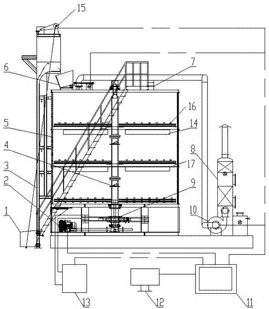
[0017] Example: Mix agricultural waste and return waste according to a certain ratio, drive the feeding silo 1 to lift through the elevator 15 (the lifting frame body 3 plays a supporting role), enter the fermentation silo 5 through the feed port 6, and The stirring device 4 and the waste fall down layer by layer under the action of its own gravity, and oxygen is sent to the waste through the vortex air pump 2, so that the waste undergoes sufficient aerobic fermentation and decomposition. The fermentation process lasts for 8 days, and the heat released during the decomposition process It can increase the temperature of the mixed waste itself, up to about 70°C, so that the water in the waste evaporates, and some organic matter is decomposed and decomposed, so as to achieve the purpose of reduction and stabilization treatment. The control box 11 controls the hydraulic pump station 13 Oil supply is driven by a hydraulic cylinder, and the power is transmitted to the stirring device...


PUM


Abstract

The invention discloses a waste fermentation device using an overclocking technology. The device comprises a base, a fermenting silo is fixed to the top end of the base, a lifting frame body is fixed to one side wall of the fermenting silo, the top end of the lifting frame body is provided with a lifting machine by screws, a steel wire rope winds the lifting machine, the bottom end of the steel wire rope passes through the lifting frame body and is connected to a loading stock bin, the loading stock bin is located at the bottom end of the side wall of the lifting frame body, the loading stock bin is slidingly connected to the side wall of the lifting frame body, the top end of the fermenting silo is provided with a feeding inlet, the feeding inlet is located at the bottom of one side of the lifting frame body, the side wall of the bottom of the fermenting silo is provided with a cavity, a vortex gas pump, a transmission device and a hydraulic cylinder are arranged in the cavity, the transmission device is located between the vortex gas pump and the hydraulic cylinder, and an output end of the vortex gas pump extends into the fermenting silo through a conduit. The device realizes harmless treatment and resource utilization of wastes and reduces fermentation exhaust damage.

Description

technical field [0001] The invention relates to the technical field of waste treatment, in particular to a waste fermentation device equipped with overfrequency technology. Background technique [0002] Traditional fertilizer reaction devices can be divided into two types: reactor and non-reactor. The common reactors mainly include drum type, tower type, tunnel kiln type, tank type, etc. The non-reactor types include strip stack type and static stack type. etc., the principle is roughly the same, mainly through the in-depth treatment of waste with high organic content such as meal waste, livestock and poultry manure, and the use of microorganisms to decompose organic macromolecules in waste into small molecules that can be absorbed and utilized. Mineralize, decompose, and harmless the organic matter, thereby producing the required organic fertilizer. The traditional process equipment mainly uses the compost turning machine to turn over the waste and aerate the waste to make ...

Claims


Application Information

Patent Timeline
Patent Type & Authority Applications(China)
IPC IPC(8): C05F17/02
CPCC05F17/60C05F17/80C05F17/95Y02W30/40
Inventor 胡茂朝
Owner NANJING BEITE AC EQUIP CO LTD
Why Eureka
Try Eureka