Optical antenna integrating polarization, isolation, receiving and transmitting

An optical antenna and polarized light technology, applied in optics, optical components, electromagnetic transceivers, etc., can solve the asymmetry of uplink and downlink, difficulty in meeting the requirements of small satellite loads, and compatibility limitations of optical communication terminals, etc. problem, to achieve superior isolation, convenient networking, and high reliability

Pending Publication Date: 2017-07-04
NO 34 RES INST OF CHINA ELECTRONICS TECH GRP +2
View PDF6 Cites 6 Cited by
  • Summary
  • Abstract
  • Description
  • Claims
  • Application Information

AI Technical Summary

Problems solved by technology

[0004] Due to the large size and weight of the optical system with separate transceivers, it is difficult to meet the requirements of small satellite loads, so it is rarely used in satellite optical communications.
Most of the current satellite optical communication terminals use the coaxial optical system for transmitting and receiving. In order to realize the isolation of transmitting and receiving, the transmitted signal light and the received signal light use different wavelengths, or the uplink and downlink are asymmetrical, which makes the optical communication terminal compatible. Sexually restricted

Method used


Image

  • Optical antenna integrating polarization, isolation, receiving and transmitting
  • Optical antenna integrating polarization, isolation, receiving and transmitting
  • Optical antenna integrating polarization, isolation, receiving and transmitting

Examples


Embodiment 1

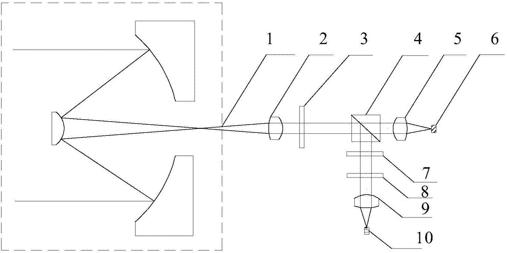
[0027] Embodiment 1 of this polarization-isolated transceiver integrated optical antenna is as follows: figure 1 As shown, it includes a laser emitting module 10, a second collimating mirror 9, a wave plate group consisting of a λ / 4 wave plate 8 and a second λ / 2 wave plate 7, a polarizing beam splitter 4, and the first λ / 2 wave plate 2 wave plate 3, collimator mirror 2, condenser mirror 5, a light receiving module 6 and an optical antenna 1.

[0028] The wavelength λ=1550nm of the laser beam emitted by the laser emitting module 10 of this example, the laser beam passes through the second collimating mirror 9 and the wave plate group composed of a λ / 4 wave plate 8 and the second λ / 2 wave plate 7, and the laser beam The linearly polarized light that becomes S-polarized, and then the reflected S-polarized light through a polarization beam splitter 4 is output to the first λ / 2 wave plate 3 without loss, and the fast axis direction and S polarization of the first λ / 2 wave plate 3 ...

Embodiment 2

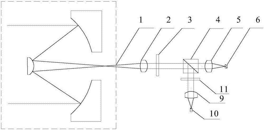
[0033] Embodiment 2 of this polarization-isolated transceiver integrated optical antenna is as follows: image 3As shown, its structure is similar to that of Embodiment 1, except that the wave plate group consisting of a λ / 4 wave plate 8 and a second λ / 2 wave plate 7 in Embodiment 1 is replaced by a modulating S-polarized linearly polarized light. Polarizer 11.


PUM


Abstract

The invention provides an optical antenna integrating polarization, isolation, receiving and transmitting. A laser beam of a laser emission module passes a wave plate group formed by a lambda/4 wave plate and a second lambda/2 wave plate to become S linearly polarized light. The S linearly polarized light reaches a first lambda/2 wave plate through a polarization beam splitter to be modulated into linearly polarized light, wherein an angle of 45 degrees is formed between the linearly polarized light and the original polarization direction. The linearly polarized light is emitted through a collimating mirror and an optical antenna. During receiving, an incidence light signal received by the optical antenna reaches the first lambda/2 wave plate through the collimating mirror, and is subjected to transmission and modulated into linearly polarized light of P polarization. The linearly polarized light of P polarization is output in a lossless manner through the polarization beam splitter, reaches an optical receiving module through a light gathering mirror and then is received by a detector of the optical receiving module. The optical path of the receiving light output by the polarization beam splitter is perpendicular to the optical path of the emission light entering the polarization beam splitter. The same optical antenna of the receiving end is arranged opposite to the emission end. An angle of 45 degrees is formed between fast axes of the first lambda/2 wave sheets of the receiving end and the emission end. Thus, weight and size of the system are greatly reduced; networking is convenient to perform; reliability is high; receiving signal to noise ratio is improved; and the optical antenna is especially suitable for satellite optical communication.

Description

technical field [0001] The invention belongs to the technical field of space laser communication, and in particular relates to a polarization-isolated transceiver integrated optical antenna. Background technique [0002] At this stage, with the development of space applications and the substantial increase in the demand for various information, especially satellite laser communication technology has become an important research direction in the field of large-capacity and high-speed space communication. This technology uses laser as an information carrier for information exchange and transmission, and has broad military and civilian application prospects. Due to its great advantages in transmission rate, capacity, volume, weight and power consumption, the United States, Europe, Japan and other countries have fully launched research work in this field, and have completed many satellite-ground and inter-satellite laser communication experiments . [0003] Space resources can...

Claims


Application Information

Patent Timeline
Patent Type & Authority Applications(China)
IPC IPC(8): G02B27/28H04B10/40
CPCH04B10/40G02B27/28
Inventor 马建军马拥华覃智祥郭军卫斌甘润蒋相鲁文杰
Owner NO 34 RES INST OF CHINA ELECTRONICS TECH GRP
Why Eureka
Try Eureka