Method for preparing carbon fiber composite material interface layer

A composite material and carbon fiber technology, applied in carbon fiber, fiber processing, textiles and papermaking, etc., can solve the problems of carbon fiber performance impact and complexity, and achieve the effects of reducing impact, adjustable thickness, and reducing damage

Active Publication Date: 2017-07-07
NINGBO INST OF MATERIALS TECH & ENG CHINESE ACADEMY OF SCI
View PDF4 Cites 6 Cited by
  • Summary
  • Abstract
  • Description
  • Claims
  • Application Information

AI Technical Summary

Problems solved by technology

However, these two methods are more complicated, especially the CVD method will also have a certain impact on the performance of the carbon fiber itself

Method used


Image

  • Method for preparing carbon fiber composite material interface layer
  • Method for preparing carbon fiber composite material interface layer
  • Method for preparing carbon fiber composite material interface layer

Examples


Embodiment 1

[0036] In this embodiment, a surface layer is prepared on the surface of the carbon fiber material, as follows:

[0037] (1) Mix acidified carbon nanotubes, PFNH-200 phenolic resin, curing agent hexamethylenetetramine, and DMF, stir evenly, and then ultrasonicate in a water bath for 30 minutes, then crush and ultrasonicate at 600w for 90 minutes to obtain a sizing agent, in which the concentration of acidified carbon nanotubes The concentration of PFNH-200 phenolic resin is 5mg / ml, and the concentration of curing agent hexamethylenetetramine is 0.5mg / ml.

[0038] (2) Sizing the carbon fiber surface with the sizing agent in step (1), and the sizing time is 30s; then drying and curing the sized carbon fiber.

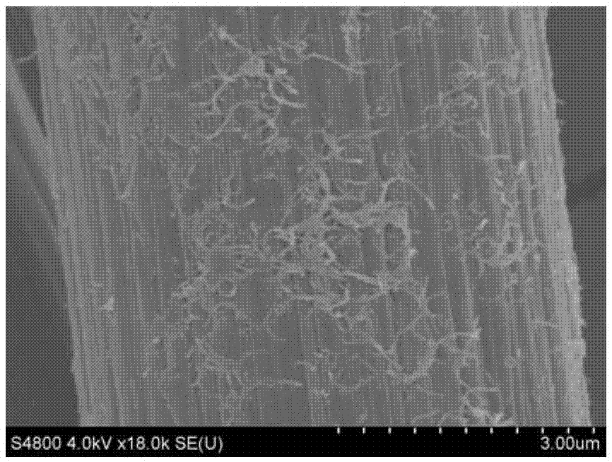
[0039] The scanning electron microscope picture of the carbon fiber after the above treatment is as follows figure 1 As shown, it can be seen that carbon nanotubes are evenly distributed on the surface of the carbon fiber matrix, and there are traces of resin on the surfa...

Embodiment 2

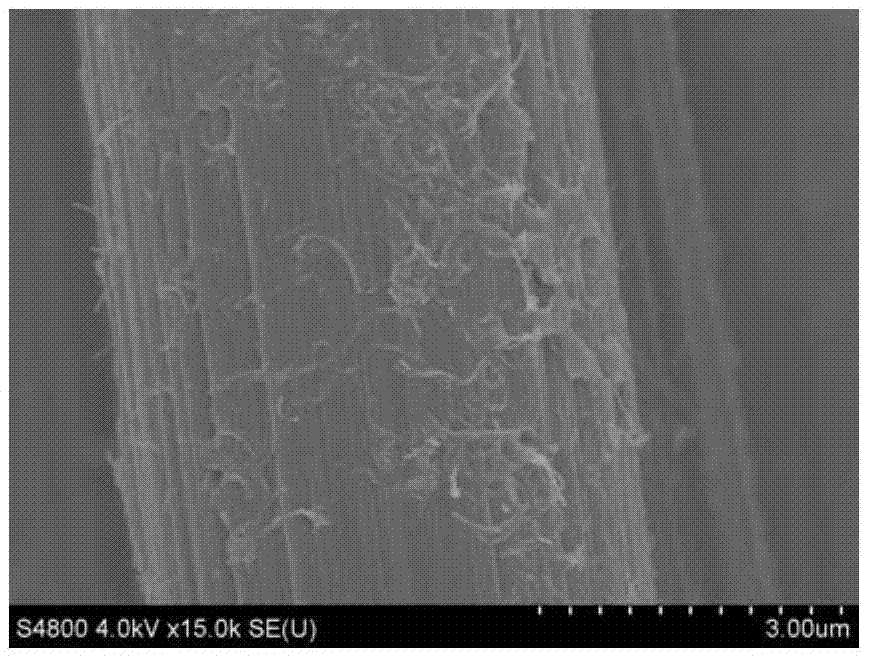
[0041] In this example, the carbon fiber material is exactly the same as that in Example 1, and the surface layer is prepared on the surface of the carbon fiber. The preparation method is basically the same as that of Example 1, except that ethanol is used instead of DMF as the solvent in the sizing agent.

[0042] The scanning electron microscope image of the treated carbon fiber is as follows: figure 2 As shown, it can be seen that carbon nanotubes are evenly distributed on the surface of the carbon fiber matrix, and resin is obviously attached to the surface.

Embodiment 3

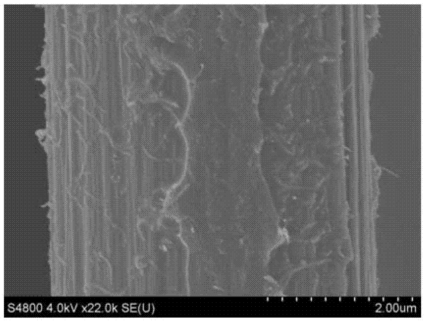
[0044] In this embodiment, the carbon fiber material is exactly the same as that in Example 1, and the surface layer is prepared on the surface of the carbon fiber. The preparation method is basically the same as in Example 1, except that the concentration of the phenolic resin in the sizing agent is 10mg / ml, The concentration of curing agent was 1 mg / ml.

[0045] The scanning electron microscope image of the treated carbon fiber is as follows: image 3 As shown, it can be seen that carbon nanotubes are evenly adsorbed on the surface of carbon fibers, and a layer of resin is attached to the entire surface of carbon fibers.


PUM

PropertyMeasurementUnit
diameteraaaaaaaaaa

Abstract

The invention provides a method for preparing a carbon fiber composite material interface layer. The method comprises the following steps: coating the surface of a carbon fiber by using a sizing agent with carbon nanotubes, phenolic resin, a curing agent and a solvent, curing, and performing high temperature thermal treatment, thereby obtaining a pyrolytic carbon coated layer with the carbon nanotubes. Effects of strengthening and toughening can be achieved in a composite material with the carbon fiber as a reinforcing part. The method is simple and feasible and low in cost, the process complexity of the method is greatly reduced as compared with those of conventional CVD and EPD, in addition, process conditions are easy to control, the carbon fiber self is not damaged in the preparation process, and the influence upon the performance of the carbon fiber self is reduced.

Description

technical field [0001] The invention relates to the technical field of surface treatment, in particular to a method for preparing an interface layer of a carbon fiber composite material. Background technique [0002] Due to its high specific strength, high specific modulus and certain toughness, carbon fiber is widely used as composite material reinforcement in aerospace, civil engineering, automobile, sports and leisure products and other fields. [0003] For composite materials, the interface plays a key role in transmitting load and dissipating energy. In the process of preparing carbon fiber composites, especially for ceramic matrix composites, it has been reported that a pyrolytic carbon coating (CVD method) or carbon nanotube layer is introduced on the surface of the carbon fiber, and the interface buffer load of the pyrolytic carbon coating is used to reduce the impact on the carbon fiber. For the damage of its own strength, carbon nanotubes are used to hinder the ex...

Claims


Application Information

Patent Timeline
Patent Type & Authority Applications(China)
IPC IPC(8): D06M11/74D06M15/41C08K9/02C08K9/04C08K7/06D06M101/40
CPCC08K7/06C08K9/02C08K9/04D06M11/74D06M15/41D06M2101/40
Inventor 王杰何流黄庆李勉季鹏钟希强杨建行
Owner NINGBO INST OF MATERIALS TECH & ENG CHINESE ACADEMY OF SCI
Why Eureka
Try Eureka