
Torsion and displacement measuring sensor based on optical fiber acousto-optic modulation

A technology of displacement sensors and acousto-optic modulators, which is applied in measuring devices, instruments, and optical devices, etc., can solve the problems of complex and slow processing methods of spectral measurement receivers, difficulty in achieving high-speed dynamic monitoring, and unsuitable for reducing sensor costs. , to achieve the effect of being easy to be built, insensitive to temperature and axial stress, and strong in anti-cross-sensitivity

Inactive Publication Date: 2017-07-11
BEIJING JIAOTONG UNIV
View PDF5 Cites 5 Cited by
  • Summary
  • Abstract
  • Description
  • Claims
  • Application Information

AI Technical Summary

Problems solved by technology

[0006] The traditional angular twist is not only sensitive to torsion and displacement, but also sensitive to the ambient temperature and the axial stress of the fiber. This cross-sensitivity leads to inaccurate sensing of torsion and displacement at the output end.
[0007] Traditional optical fiber sensors generally use spectrometry to measure changes in the wavelength and amplitude of the output light spectrum, while the spectral measurement receiver processing method is complex, slow and expensive, so it is difficult to achieve high-speed dynamic monitoring and is not suitable for reducing the entire sensor. cost

Method used


Image

  • Torsion and displacement measuring sensor based on optical fiber acousto-optic modulation
  • Torsion and displacement measuring sensor based on optical fiber acousto-optic modulation

Examples


Embodiment Construction

[0017] The preferred modes of the present invention will be further described in detail below in conjunction with the accompanying drawings. It should be understood that the specific embodiments described here are only used to explain the present invention, not to limit the present invention.

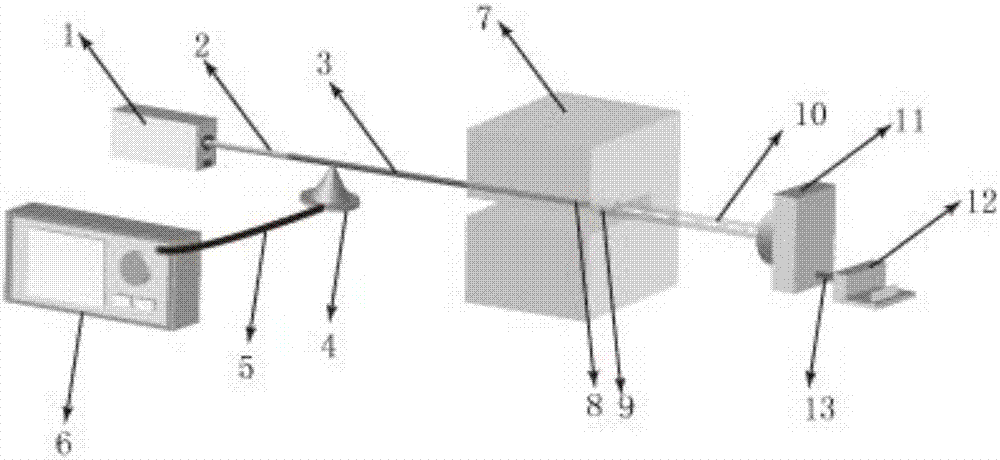
[0018] A sensor for measuring torsion and displacement based on optical fiber acousto-optic modulation (see figure 1 ) includes a laser 1, a single-mode fiber 2, a two-mode fiber 3, a piezoelectric ceramic acousto-optic modulator 4, wires 5 and 13, a microwave signal generator 6, a measured object 7, a two-mode fiber end 8, and a zoom collimator lens 9. Transmission light beam 10, CCD camera 11 and data processor 12; wherein the laser 1 is directly connected to the single-mode fiber 2, the single-mode fiber 2 is directly connected to the second-mode fiber 3, and the second-mode fiber 3 is tightly attached to the piezoelectric ceramic acoustic On the optical modulator 4, the piezoelectr...


PUM


Abstract

The invention relates to an optical fiber acousto-optic torsion and displacement sensor and more particularly, to a torsion and displacement sensor arranged on an acousto-optic modulator based on a few-mode or multi-mode optical fiber. The optical fiber acousto-optic torsion and displacement sensor of the invention, more particularly, relates to a torsion and displacement sensor arranged on an acousto-optic modulator based on a few-mode or multi-mode optical fiber. The sensor of the invention is designed to overcome the axial angle torsion in construction structure security and internal damage detection as well as the shortcomings of the current technology of a micro displacement sensor and therefore, an optical fiber acousto-optic torsion and displacement sensor suitable for use in a micro space dangerous environment is provided. Through the transmission of detection light in different modes by the optical fiber acousto-optic modulator through one single few-mode optical fiber, the detection light is converted by the different angle torsions and the micro displacement amounts of a detected object into the torsion amount and the displacement amount of an image monitoring and capturing system; and an image identifying algorithm realizes the dynamic monitoring. According to the invention, in a dangerous environment, the sensor can simultaneously the axial torsion and the three-dimensional micro displacement of a detected object, and is not provided with the intersecting sensitivity between the temperature and the axial stress, therefore, capable of being created by a cost-effective image identifying system.

Description

technical field [0001] The invention relates to an optical fiber acousto-optic torsion and displacement sensor, in particular to a torsion and displacement sensor based on setting up an acousto-optic modulator on a few-mode or multi-mode optical fiber. Background technique [0002] With the continuous development of large-scale infrastructure (such as bridges, hydropower stations, roads and railways, etc.), intelligent buildings, mechanical devices and high-risk environment buildings (such as chemical warehouses, oil storage depots and nuclear power plants, etc.), the safety of building structures and internal damage detection demand has grown dramatically. The angular torsion of the central axis and the three-dimensional micro-displacement in space are important indicators for detecting structural damage and internal safety. Due to the limitation of the narrow space scale, the traditional large-area contact sensor cannot place the sensing head inside the building, resultin...

Claims


Application Information

Patent Timeline
IPC IPC(8): G01B11/26G01B11/02
CPCG01B11/26G01B11/02
Inventor 任国斌刘昱任文旭
Owner BEIJING JIAOTONG UNIV
Learn More