
Method for treating refrigerant with freon and equipment of method

A refrigerant and freon technology, which is applied in the field of dealing with freon refrigerants, can solve the problems of resource waste, refrigerant danger, high power consumption, etc., and achieve the effect of avoiding heat loss and easy catalyst

Inactive Publication Date: 2017-07-21
HEFEI JINTONGWEI LOW TEMPERATURE TECH CO LTD
View PDF4 Cites 0 Cited by
  • Summary
  • Abstract
  • Description
  • Claims
  • Application Information

AI Technical Summary

Problems solved by technology

[0003] Refrigerators of the 1920s used a number of toxic and dangerous gases, including ammonia, sulfur dioxide, and propane, as refrigerants that were dangerous due to frequent leaks
[0005] At present, in the recycling of household appliances such as refrigerators and air conditioners, Freon will be collected separately. Most of Freon’s treatment is by combustion. The cost of microwave decomposition and plasma methods is too high. For Freon used in large refrigerators or refrigeration workshops, the combustion method will produce New pollutants, and consume a lot of electricity, produce new pollutants that cannot be recycled, resulting in waste of resources, not suitable for industrialized treatment

Method used


Image

  • Method for treating refrigerant with freon and equipment of method

Examples


Embodiment 1

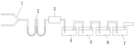
[0022] like figure 1 The method for treating refrigerants with Freon is to dehydrate and dry aluminum sulfate, copper sulfate, and aluminum phosphate to make them into granules. In the reactor 2, a tee pipe 1 is arranged at the inlet end of the U-shaped reactor 2, and the outlet end of the tee pipe 1 is connected with the inlet end of the U-shaped reactor.

[0023] The inlet ends of the three-way pipe 1 are respectively supplied with water vapor and refrigerant with Freon, and the volume flow of the water vapor is twice that of the refrigerant with Freon. The water vapor and the refrigerant with Freon are introduced into the U-shaped reactor 2 at the same time, and the flow rate of the water vapor and the air flow with the refrigerant with Freon are controlled, so that the refrigerant with Freon and the water vapor are in contact with the catalyst for 2min. The air flow out of the U-shaped reactor 2 is cooled to below 10°C by a heat exchanger, then passes through anhydrous co...

Embodiment 2

[0031] like figure 1 The method for treating refrigerants with Freon is to dehydrate and dry aluminum sulfate, copper sulfate, and aluminum phosphate to make them into granules. In the reactor 2, a tee pipe 1 is arranged at the inlet end of the U-shaped reactor 2, and the outlet end of the tee pipe 1 is connected with the inlet end of the U-shaped reactor.

[0032] The inlet ends of the three-way pipe 1 are respectively fed with water vapor and refrigerant with Freon, and the volume flow of the water vapor is three times that of the refrigerant with Freon. The water vapor and the refrigerant with Freon are passed into the U-shaped reactor 2 at the same time, and the flow rate of the water vapor and the air flow with the refrigerant with Freon are controlled, so that the refrigerant with Freon and the water vapor are in contact with the catalyst at 6min. The air flow out of the U-shaped reactor is cooled to below 10°C by a heat exchanger, then passes through anhydrous copper s...

Embodiment 3

[0041] like figure 1 The method for treating refrigerants with Freon is to dehydrate and dry aluminum sulfate, copper sulfate, and aluminum phosphate to make them into granules. In the reactor 2, a tee pipe 1 is arranged at the inlet end of the U-shaped reactor 2, and the outlet end of the tee pipe 1 is connected with the inlet end of the U-shaped reactor.

[0042]The inlet ends of the three-way pipe 1 are respectively fed with water vapor and refrigerant with Freon, and the volume flow of the water vapor is three times that of the refrigerant with Freon. The water vapor and the refrigerant with Freon are passed into the U-shaped reactor 2 at the same time, and the flow rate of the water vapor and the air flow with the refrigerant with Freon are controlled, so that the refrigerant with Freon and the water vapor are in contact with the catalyst at 6min. The air flow out of the U-shaped reactor 2 is cooled to below 10°C by a heat exchanger, then passes through anhydrous copper ...


PUM


Abstract

Disclosed are a method for treating a refrigerant with freon and equipment of the method. The method comprises the following steps that aluminum sulfate, copper sulfate and aluminum phosphate are subjected to dehydration and drying and are made into particles, after sieving, the particles are mixed evenly according to a certain ratio, an appropriate amount of water is added, and a catalyst is formed; the catalyst is put into a U-shaped reactor, vapor and the refrigerant with the freon are led into the U-shaped reactor simultaneously, the flow speed of the vapor and airflow of the refrigerant with the freon are controlled, and thus the contact time of the refrigerant with the freon as well as the vapor and the catalyst is 2-6 min; and the airflow getting out of the U-shaped reactor is cooled to 10 DEG C or below through a heat exchanger, then the airflow passes through anhydrous cupric sulfate, absolute ethyl alcohol, water and a sodium hydroxide solution sequentially, and finally, mixed gas is discharged into the atmosphere. Through the method for treating the refrigerant with the freon and the equipment of the method, the decomposition rate of the Freon can reach 90% or above, the process is simple and easy to achieve, the used catalyst is easy to obtain and cheap, products obtain through hydrolysis can be reused, and secondary pollution to the environment is avoided.

Description

technical field [0001] The invention belongs to the field of waste gas treatment, and in particular relates to a method and equipment for treating refrigerant with freon. Background technique [0002] Freon is one of the ozone-depleting substances, and it is one of the culprits in destroying the ozone layer. Freon was synthesized in the 1920s. Its chemical properties are stable, and it is not flammable and toxic. It is often used to make refrigerants and is widely used. For air conditioners, refrigerators and other refrigeration appliances. In the late 1980s, the production of Freon reached a peak, with an output of 1.44 million tons. Before the control of Freon, the world's emission of Freon into the atmosphere had reached 20 million tons. Because of their average lifetime in the atmosphere of hundreds of years, it is a greenhouse gas that permanently destroys the ozone layer. [0003] Refrigerators of the 1920s used some toxic and dangerous gases, including ammonia, sul...

Claims


Application Information

Patent Timeline
IPC IPC(8): F25B43/00
CPCF25B43/00
Inventor 武行峰
Owner HEFEI JINTONGWEI LOW TEMPERATURE TECH CO LTD
Learn More