Piston rotation type internal combustion engine
A kind of internal combustion engine, rotary technology, applied in the direction of internal combustion piston engine, combustion engine, mechanical equipment, etc., can solve the problems of the piston ring and the cylinder cannot be effectively lubricated, and the multiple units cannot be effectively combined, etc., and achieves light weight, compact structure, and fewer failures. Effect
- Summary
- Abstract
- Description
- Claims
- Application Information
AI Technical Summary
Problems solved by technology
Method used
Image
Examples
Embodiment approach 1
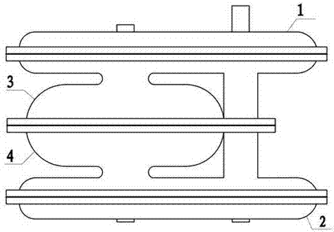
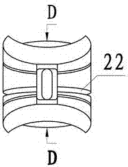
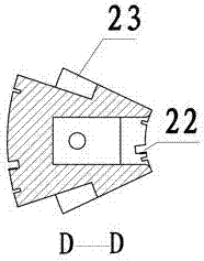
[0069] Implementation method one: the structure includes two ring-shaped cylinders 3 and 4 whose inner cross-sections are semicircular to form a set of annular cylinders whose inner cross-sections are circular. The outside of the sleeve is designed according to the cooling requirements; the gear box is set on both sides of the cylinder, such as figure 1 , 2 , 3, 4, and 5; the cylinder block is provided with a strip-shaped air intake hole 20 and an exhaust hole 21, and the strip shape of the intake and exhaust holes is arranged according to the direction of piston rotation. One end of the hole in the forward direction of the piston can be set in a circular arc shape, and the other end can be flush, so that the piston ring can pass smoothly while quickly completing the intake and exhaust; especially at the beginning of the exhaust port, The exhaust port can be opened wider, so that the angle of the exhaust advance angle can be reduced as much as possible, so as to facilitate t...
Embodiment approach 2
[0070] Implementation method 2: Two annular cylinder blocks 42, 43 with semicircular inner cross sections are provided to form a set of circular annular cylinder blocks with circular inner cross sections, which are combined with the gear box cover 41 to form a set of internal combustion engine cylinder blocks; The gears are all arranged on the same side of the cylinder block, and two rotors 12, 13 are housed inside, and two rotor shafts 39, 40 are installed on the two rotors respectively; The circular gear 8 and the rotor 13 are connected and assembled as one, and the rotor shaft 40 passes through the rotor shaft 39 to connect and assemble the non-circular gear 7 and the rotor 12 as one, as Figure 31 , 32 As shown; in addition, the center of the rotor shaft 40 is provided with a lubricating oil passage, and the lubricating oil passage is drawn from the middle part of the two rotors for the lubricating oil to flow out for lubrication between the two rotors (not shown in the fi...
Embodiment approach 3
[0071] Implementation method three: on the basis of implementation method one, two sets of internal combustion engines are connected in parallel, two non-circular gears 7 and two non-circular gears 8, one eccentric gear 9 and one eccentric gear 10, two non-circular gears Mesh with one of the eccentric gears together, and output power through a power output shaft; Figure 33 , 34 , 35, and 36, 8 pistons are respectively assembled in two cylinders, and the distribution of cylinders and pistons is as follows Figure 39 shown.
PUM
 Abstract
Description
Claims
Application Information
 - R&D
- Intellectual Property
- Life Sciences
- Materials
- Tech Scout
- Unparalleled Data Quality
- Higher Quality Content
- 60% Fewer Hallucinations
Browse by: Latest US Patents, China's latest patents, Technical Efficacy Thesaurus, Application Domain, Technology Topic, Popular Technical Reports.
© 2025 PatSnap. All rights reserved.Legal|Privacy policy|Modern Slavery Act Transparency Statement|Sitemap|About US| Contact US: help@patsnap.com


