Coating structure, heat exchanger, and method for manufacturing heat exchanger

A heat exchanger and coating technology, which is applied in the manufacture of heat exchangers and heat exchangers, and in the field of coating structure, can solve the problems of atomic layer deposition method surface reaction hindrance, poor formation of insulating film, etc.

Inactive Publication Date: 2017-08-01
DENSO CORP
View PDF9 Cites 0 Cited by
  • Summary
  • Abstract
  • Description
  • Claims
  • Application Information

AI Technical Summary

Problems solved by technology

Therefore, there is a concern that it is very easily affected by the surface of the substrate, and if there are foreign substances on the surface of the substrate, the surface reaction of the atomic layer deposition method at that part will be hindered.
As a result, there are cases where no film is formed at the portion where the foreign matter exists on the surface of the base material, and poor formation (defect) of the insulating film occurs.

Method used


Image

  • Coating structure, heat exchanger, and method for manufacturing heat exchanger
  • Coating structure, heat exchanger, and method for manufacturing heat exchanger
  • Coating structure, heat exchanger, and method for manufacturing heat exchanger

Examples


no. 1 approach

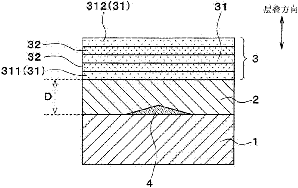
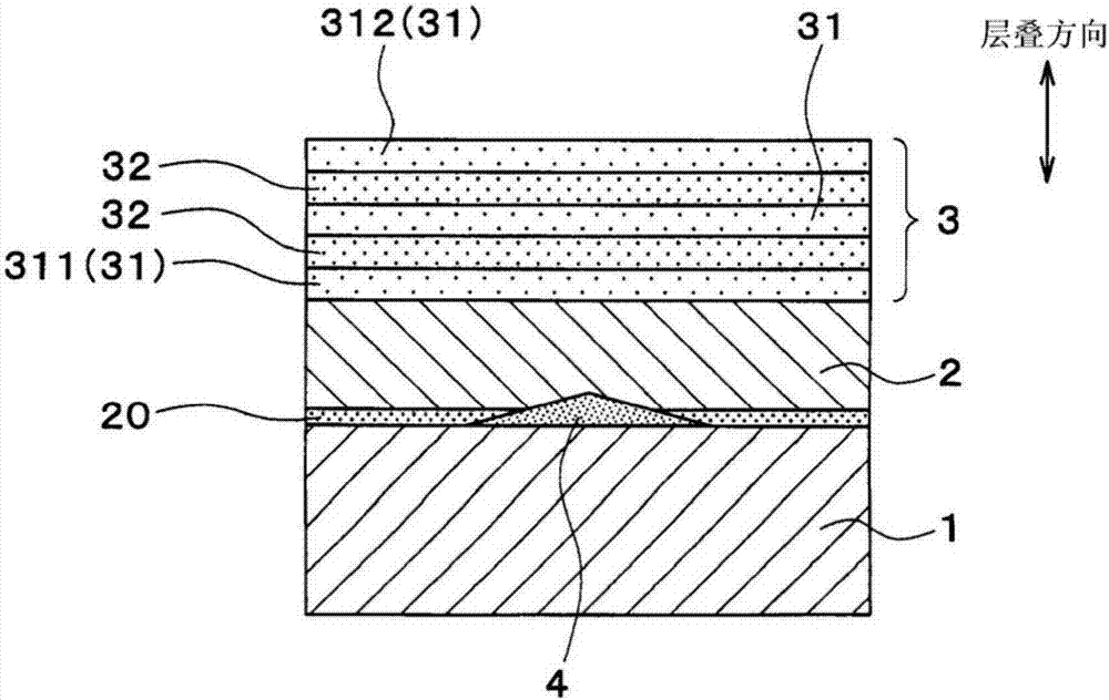
[0027] Below, based on figure 1 and figure 2 A first embodiment of the present invention will be described. In this embodiment, an example in which the coating structure of the present invention is applied to an exhaust pipe through which exhaust gas from an internal combustion engine flows will be described.

[0028] Such as figure 1 As shown, the exhaust pipe is formed with a base material 1 made of metal. In this embodiment, the base material 1 is formed of stainless steel or aluminum.

[0029] A substrate 2 is formed above the substrate 1 , that is, on the surface of the substrate 1 . An insulating film 3 is formed above the base 2 , that is, on the surface of the base 2 opposite to the substrate 1 .

[0030] The base 2 improves the adhesion between the base material 1 and the insulating film 3 . The substrate 2 of the present embodiment is made of amorphous silicon carbide (SiC) or aluminum oxide (Al 2 o 3 ) composed of a monolayer film. In addition, the thickne...

no. 2 approach

[0056] Next, based on Figure 5 A second embodiment of the present invention will be described. This second embodiment differs from the first embodiment in the structure of the base 2 .

[0057] Such as Figure 5 As shown, the substrate 2 of the present embodiment is formed by alternately stacking a plurality of amorphous layers 21 made of amorphous and crystalline layers 22 made of crystalline crystals. In the base 2 , an amorphous layer 21 is arranged at a portion in contact with the base material 1 and a portion in contact with the insulating film 3 . That is, in the base 2 , the portions in contact with the base material 1 and the portions in contact with the insulating film 3 are respectively amorphous.

[0058] As described above, in the base 2 , the portion in contact with the base 1 is made amorphous, so that the adhesiveness between the base 1 and the base 2 can be improved. In addition, in the base 2 , the portion in contact with the insulating film 3 is made amo...


PUM

PropertyMeasurementUnit
thicknessaaaaaaaaaa
thicknessaaaaaaaaaa

Abstract

A coating structure is provided with a metal-made substrate (1), an undercoating (2) provided on the substrate, and an insulating film (3) provided on the undercoating. The insulating film has a plurality of films (31, 32) comprising mutually different materials, and the plurality of films are layered in alternating fashion. The undercoating is formed by a method other than a coating method which uses a surface chemical reaction occurring on the substrate, and the portion of the undercoating in contact with the substrate is amorphous. Through this configuration, even when foreign matter adheres to the substrate, the foreign matter can be covered by the undercoating. Providing the insulating film on the undercoating makes it possible to inhibit foreign matter from causing defects in the formation of the insulating film.

Description

[0001] Cross-references to related applications [0002] This application is based on Japanese Patent Application No. 2014-243979 filed on December 2, 2014 and Japanese Patent Application No. 2015-215172 filed on October 30, 2015, and the disclosures thereof are incorporated herein by reference. technical field [0003] The present invention relates to a coating structure, a heat exchanger and a method of manufacturing the heat exchanger. Background technique [0004] Conventionally, an insulating film is formed on the surface of a semiconductor substrate (for example, refer to Patent Document 1). As a technique for forming such an insulating film on a semiconductor substrate, atomic layer deposition (Atomic Layer Deposition; ALD) is known. [0005] However, it is necessary to have corrosion resistance to an exhaust gas distribution part (for example, an exhaust pipe, etc.) through which exhaust gas discharged from an internal combustion engine of a vehicle circulates. The...

Claims


Application Information

Patent Timeline
Patent Type & Authority Applications(China)
IPC IPC(8): C23C16/02C23C16/40C23C16/42F01N13/16
CPCF01N13/08F01N13/18F01N2510/08C23C16/0272C23C16/45529C23C16/45555C23C16/02C23C16/325C23C16/40C23C16/403C23C18/1216C23C18/1254C23C28/04F01N13/16C23C16/42
Inventor 加福一彰佐野幸浩林孝幸富坂学寺亮之介
Owner DENSO CORP
Why Eureka
Try Eureka