A regulator rectifier device and a method for regulating an output voltage of the same

A rectifier device and output voltage technology, applied in the direction of converting AC power input to DC power output, circuit devices, battery circuit devices, etc., can solve problems such as insufficient efficiency and loss of control of a single phase.

Active Publication Date: 2017-08-01
FLASH ELECTRONICS INDIA
View PDF6 Cites 3 Cited by
  • Summary
  • Abstract
  • Description
  • Claims
  • Application Information

AI Technical Summary

Problems solved by technology

But this method of using a timer to control the MOSFETs is not efficient enough in providing a full control technique because during the timer phase, a single phase loses control

Method used


Image

  • A regulator rectifier device and a method for regulating an output voltage of the same
  • A regulator rectifier device and a method for regulating an output voltage of the same
  • A regulator rectifier device and a method for regulating an output voltage of the same

Examples


Embodiment Construction

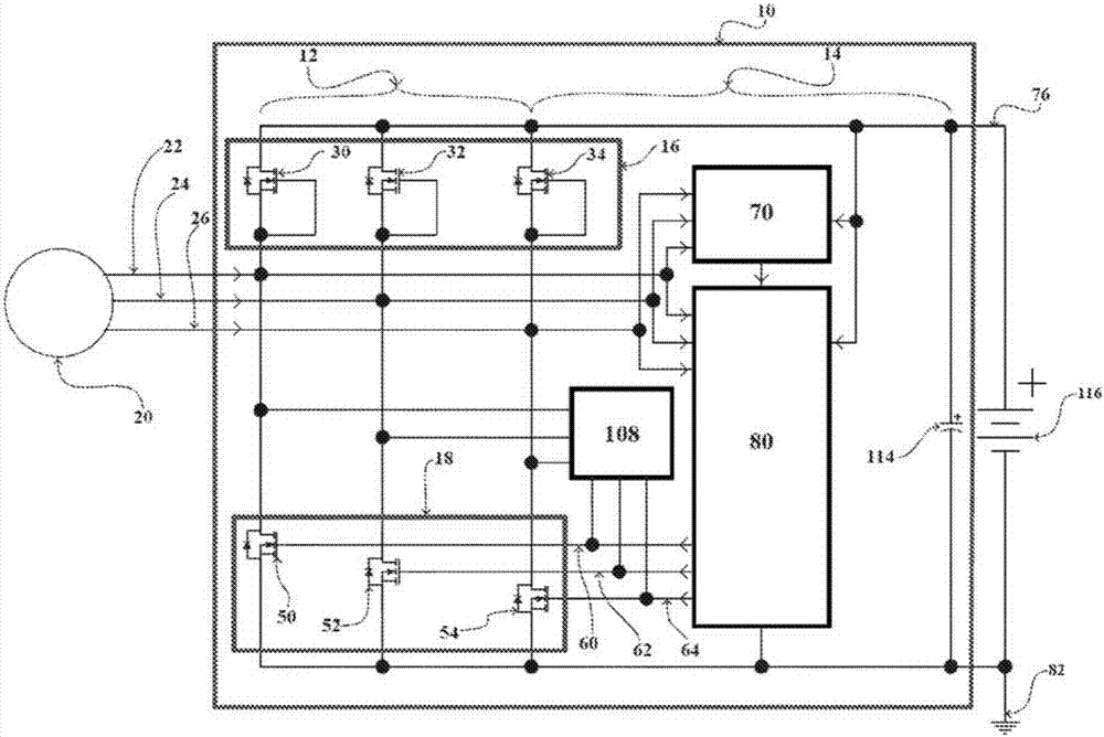
[0075] A full understanding of the invention may be best understood by reading the following detailed description of an embodiment of a regulation rectifier 10 and a method of regulating the output voltage 76 of the trim rectifier with respect to ground 82 . Wherein, the regulating and rectifying device 10 includes a source terminal for receiving three-phase AC voltage from the generating device 20 , and the generating device 20 is connected to the rectifying unit of the rectifying part 12 and connected to the control unit 80 in the controlling part 14 .

[0076] Such as figure 1 As shown, the power generating device 20 inputs a three-phase AC voltage, wherein each phase includes a positive cycle and a negative cycle. The three phases include R phase 22 , Y phase 24 and B phase 26 . Each of these three phases includes a positive cycle and a negative cycle. The power generating device 20 is connected to rectification units for both positive rectification and negative rectific...


PUM


Abstract

A regulator rectifier device and a method for regulating an output voltage of the same which takes input from three phase alternating current voltage generating device with each phase including a positive cycle and a negative cycle. A first rectifying unit with a first gate terminal, connected to the generating device to rectify the positive cycle of said three phase alternating current voltage. A second rectifying unit with a second gate terminal, connected to said generating device to rectify the negative cycle of said three phase alternating current voltage, wherein said second rectifying unit switches between rectification mode and shunt mode depending on the load condition. And a controlling unit configured to control said second rectifying unit by a gate control signal, said controlling unit outputs said gate control signal based on an output voltage of said regulator rectifier device with respect to a first predefined voltage in battery connected condition or third predefined voltage in battery-less condition and said positive cycle and said negative cycle of each phase of said three phase alternating current voltage from said generating device, said gate control signal enables said second rectifying unit to switch between rectification mode and shunt mode by controlling the second gate terminal of said second rectifying unit, wherein said gate control signal switches said second rectifying unit into shunt mode when the output voltage of said regulator rectifier device is greater than said first predefined voltage in battery connected condition or third predefined voltage in battery-less condition and thereby continuing the shunting of said second rectifying unit as long as said positive cycle of corresponding phase of said three phase alternating current voltage exists.

Description

technical field [0001] The invention relates to a regulating rectifier and a method for regulating its output voltage. More specifically, the present invention relates to an automotive regulation and rectification device based on Metal-Oxide-Semiconductor Field-Effect Transistor (MOSFET) for efficiently charging batteries and providing Various electrical devices or electronic devices (such as electronic control unit, Electronic Control Unit, ECU), lighting load, various sensors, solenoids or fuel injectors, etc.) supply energy. Background technique [0002] Voltage rectification from AC voltage to DC voltage has been very common since the past many years. Diodes are the most common components used to rectify AC voltage in either half-wave or full-wave mode. For car battery charging or powering some battery-powered loads, the DC voltage needs to be regulated to certain limits, which is known as regulation. For regulation, thyristor-controlled rectification using either a s...

Claims


Application Information

Patent Timeline
Patent Type & Authority Applications(China)
IPC IPC(8): H02J7/14
CPCH02J7/1492H02M7/219Y02T10/92H02J7/02H02J2207/20H02M7/2195Y02B70/10H02J7/06H02M1/084H02M7/2173
Inventor 莱米特·维尔马
Owner FLASH ELECTRONICS INDIA
Why Eureka
Try Eureka