Shielding box

A technology of shielding box and shielding layer, applied in the fields of magnetic field/electric field shielding, electrical components, metal containers, etc., can solve the problems of ineffective sealing effect, unenvironmental protection of metal plate welding process, and unenvironmental protection of sheet metal welding process. Manufacturing and labor costs, to meet standardized modularization and generalization, to ensure the effect of structural strength and stability

Active Publication Date: 2017-08-04
SHENZHEN JIACHEN TECH
View PDF9 Cites 4 Cited by
  • Summary
  • Abstract
  • Description
  • Claims
  • Application Information

AI Technical Summary

Problems solved by technology

[0005] 1). The casting process is not environmentally friendly and causes environmental pollution; the production cycle is long;
[0006] 2). The appearance and size of the product are fixed and single, which cannot quickly meet the market for a small number of diverse customized products. It is only suitable for mass production and has poor market applicability;
[0007] 3). The casting process requires a model, which requires a lot of materials and high cost;
[0008] 4). Casting products have many defects (cracks / trachoma / porosity / shrinkage cavity deformation / high internal stress, etc.); and these defects are not easy to be detected, resulting in hidden dangers in the quality of the products;
[0009] 5). There are many post-processing techniques (cleaning / polishing / machining), and the high internal stress after the finished product will cause continuous deformation during the use of the finished product;
[0010] 6). High cost does not meet the requirements of energy saving, emission reduction and lean production
[0012] 1). Metal plate welding process is not environmentally friendly, causing environmental pollution
Poor welding rigidity is easy to fall off and cause safety accidents;
[0013] 2). The welding appearance of the metal plate is not beautiful;
[0014] 3). There are many welding defects (deformation / welding holes / missing welding) on ​​the metal plate, which is not easy to seal, resulting in signal leakage; and these defects are not easy to be detected, resulting in product quality hazards;
[0015] 4).Complicated and repeated mechanical processing is required in the later stage, and the production cycle is long;
[0016] 5). The cost is high, the sealing effect is ineffective, and the yield rate is low;
[0017] 6). Does not meet the requirements of energy saving, emission reduction and lean production
[0019] 1). Sheet metal welding process is not environmentally friendly, causing environmental pollution
Poor welding rigidity is easy to fall off and cause safety accidents;
[0020] 2). The appearance of sheet metal welding is not beautiful;
[0021] 3). There are many welding defects in sheet metal (deformation / welding holes / missing welding), which are not easy to seal, resulting in signal leakage; and these defects are not easy to be detected, resulting in product quality hazards;
[0022] 4).Complicated and repeated mechanical processing is required in the later stage, and the production cycle is longer;
[0023] 5). The sheet metal process is complicated, the cost is high, the sealing effect is ineffective, and the yield rate is low;
[0024] 6). Does not meet the requirements of energy saving, emission reduction and lean production
[0026] 1). Mold forming process has high cost and long production cycle;
[0027] 2). The appearance and size of the product are fixed and single, which cannot quickly meet the current market with a small amount and variety of customization, and is only suitable for mass production, and the market applicability is very poor;
[0028] 3). Complicated mechanical processing is required in the later stage;
[0029] 4). High cost

Method used


Image

  • Shielding box
  • Shielding box
  • Shielding box

Examples


Embodiment Construction

[0071] In order to illustrate the technical solution of the present invention more clearly, the technical solution of the present invention will be further described in detail below in conjunction with the accompanying drawings and embodiments. Obviously, the following descriptions are only some embodiments of the present invention. In other words, other embodiments can also be obtained according to these embodiments without paying creative efforts.

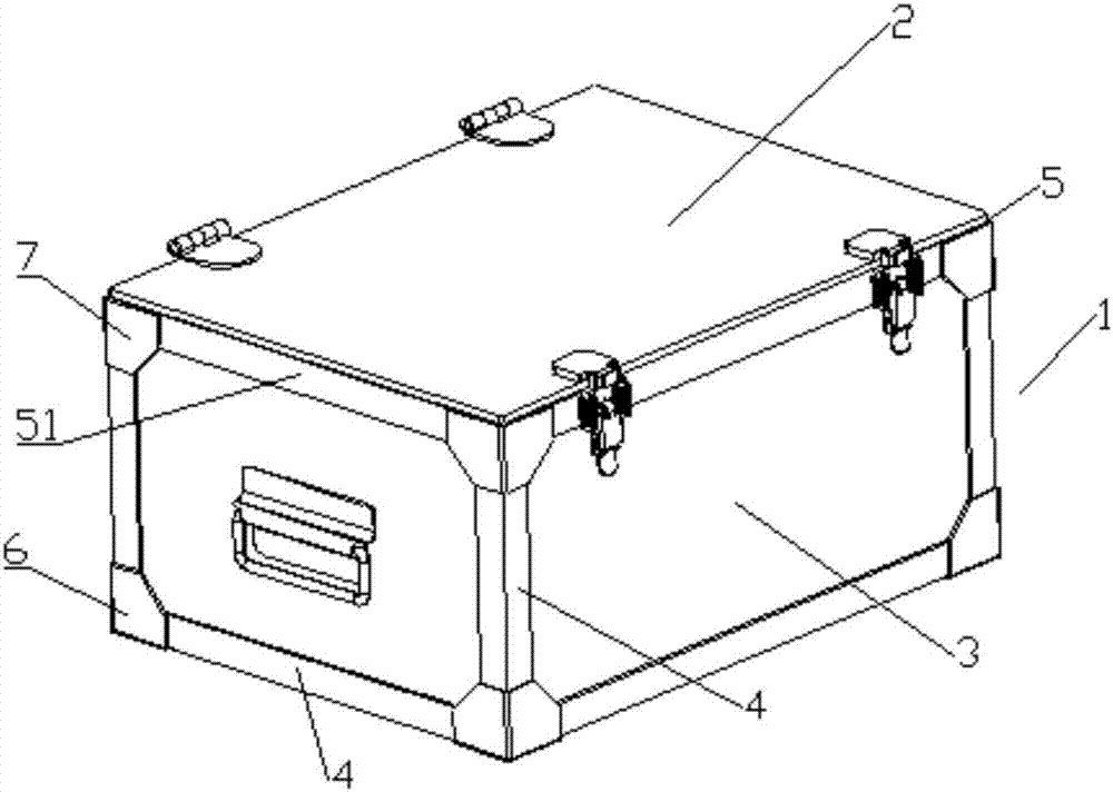
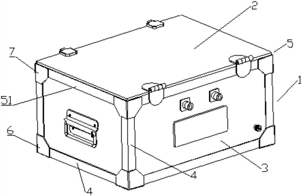
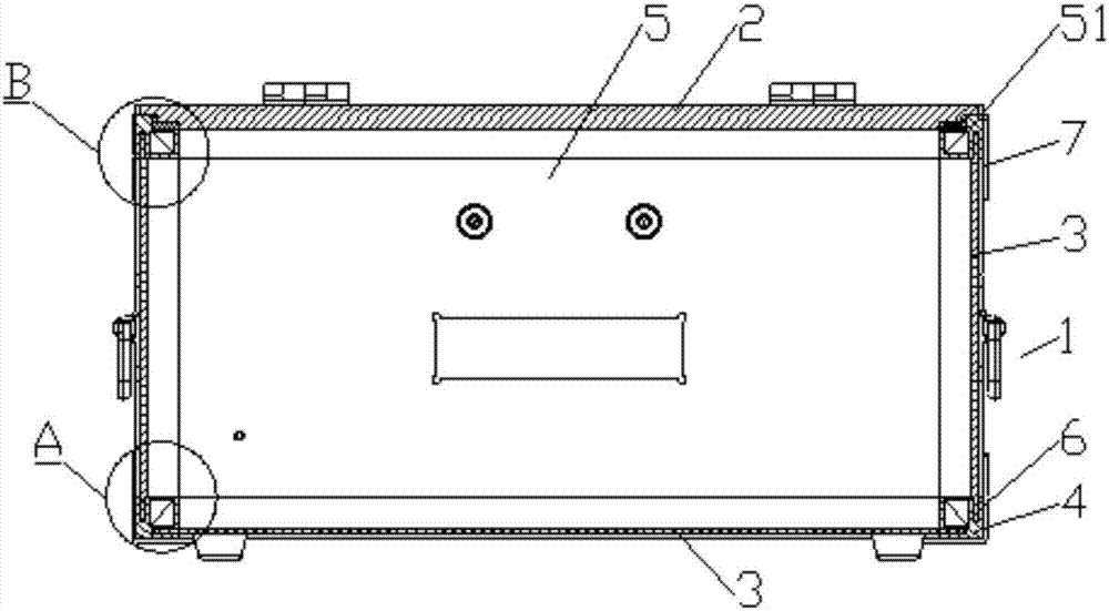
[0072] refer to Figure 1 to Figure 19 , a shielding box, including a box body 1 and a cover body 2, the main part of the box body 1 is spliced ​​by a plurality of panels 3 and a plurality of profiles, and the box body 1 has a first opening 5; the profiles are provided with The inlay groove 11 matched with the edge of the surrounding board 3, the surrounding board 3 is assembled to the profile with the edge inserted into the inlaid groove 11, and the adjacent surrounding boards 3 are assembled to the same profile. Specifically, ...


PUM


Abstract

The invention discloses a shielding box, and the shielding box comprises a box body and a cover body. The main part of the box body is formed by the jointing of a plurality of enclosing plates and a plurality of sections. Moreover, the box body is provided with a first opening. The sections are provided with inset grooves which are matched with the edges of the enclosing plates. The enclosing plates are installed on the sections in a mode of enabling the edges of the enclosing plates to be inserted into the inset grooves, and the adjacent enclosing plates are assembly on the same section. According to the invention, the shielding box is divided into universal modules to form an assembly structure, and at least has the following advantages that 1, the design and machining and assembly technology meet the requirements of environment protection, energy-saving and emission reduction and lean production; 2, the shielding box employs a section structure, is simple and convenient in design and machining, and is easy to standardize; 3, the product design can serve for the customization of a standardized product and small diversified products quickly and conveniently; 4, the sections are employed for forming the frame structure of the shielding box, and the interlacing of the sections and the strengthening of angle beads guarantee the stability of the structure.

Description

technical field [0001] The invention relates to a shielding box, in particular to a shielding box with an assembled structure that can be quickly assembled. Background technique [0002] In the existing market, the following four methods are generally used to process and manufacture shielding products: a. Casting molding + mechanical processing: through various casting processes, various box-type objects are cast, and then mechanically processed, assembled into boxes / boxes / Cabinet / house products; b. Welding and forming of metal plates + mechanical processing: through full welding or seamless welding of various metal plates, welded into various box-type objects, and then mechanically processed to assemble into boxes / box / cabinet / room products; c, sheet metal welding forming + machining: through various sheet metal materials bending full welding or seamless welding process, welded into various box-type objects, and then mechanical processing , Assembled into box / cabinet / cabi...

Claims


Application Information

Patent Timeline
Patent Type & Authority Applications(China)
IPC IPC(8): H05K9/00
CPCH05K9/0049H05K9/006
Inventor 伍连保杨伟
Owner SHENZHEN JIACHEN TECH
Why Eureka
Try Eureka