Eyepiece optical system with large field of view and high image quality and head-mounted display device

A technology for an optical system and a display device, applied in the optical field, can solve the problems of increasing the difficulty of manufacturing optical components, increasing the manufacturing cost and weight, and insufficiently uniform full-frame image quality, and achieving a high-presence visual experience, compact structure, and system image. Difference elimination effect

Active Publication Date: 2019-05-10
SHENZHEN NED OPTICS CO LTD
View PDF3 Cites 3 Cited by
  • Summary
  • Abstract
  • Description
  • Claims
  • Application Information

AI Technical Summary

Problems solved by technology

The eyepiece optical system can achieve the optical effect of super large field of view (>75 degrees), but the image quality of the peripheral field of view is lower than that of the central field of view, and the image quality of the full frame is not uniform enough. At the same time, it needs to use the refractive index Larger optical materials, in the existing known optical materials, materials with high refractive index lead to increased manufacturing cost and weight of products, and increase the difficulty of manufacturing corresponding optical elements

Method used


Image

  • Eyepiece optical system with large field of view and high image quality and head-mounted display device
  • Eyepiece optical system with large field of view and high image quality and head-mounted display device
  • Eyepiece optical system with large field of view and high image quality and head-mounted display device

Examples


Embodiment 1

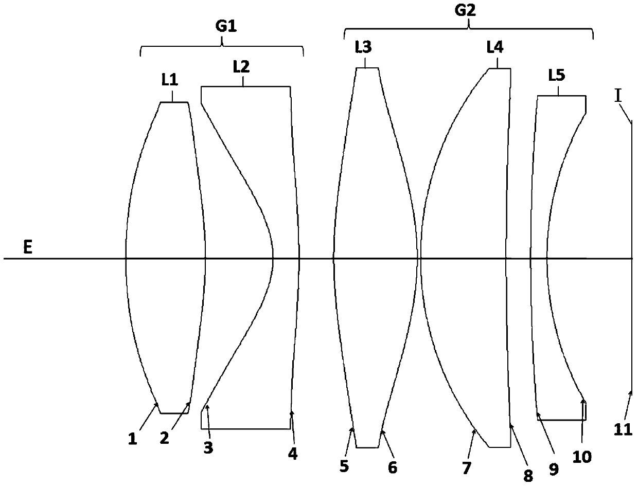
[0137] as attached figure 1 As shown, the optical path structure schematic diagram of the eyepiece optical system of the first embodiment of the present invention, from the human eye observation side to the display device I side (from left to right), is successively the diaphragm E, the first lens group G1, the second lens Group G2 and display device I. Wherein, the first lens group G1 is composed of the first lens L1 and the second lens L2, and the second lens group G2 is composed of the third lens L3, the fourth lens L4 and the fifth lens L5. In the present invention, the diaphragm E can be the exit pupil of the eyepiece optical system, which is a virtual light exit aperture. When the pupil of the human eye is at the diaphragm position, the best imaging effect can be observed. In this embodiment, the first lens L1 is a positive lens, and the second lens L2 is a negative lens, forming a first lens group G1 with negative refractive power, wherein the first lens L1 is a biconv...

Embodiment 2

[0145] as attached Figure 4 As shown, the optical path structure schematic diagram of the eyepiece optical system of the second embodiment of the present invention, from the human eye observation side to the display device I side (from left to right), is successively the diaphragm E, the first lens group G1, the second lens Group G2 and display device I. Wherein, the first lens group G1 is composed of the first lens L1 and the second lens L2, and the second lens group G2 is composed of the third lens L3, the fourth lens L4 and the fifth lens L5. In this embodiment, the first lens L1 is a positive lens, and the second lens L2 is a negative lens, forming a first lens group G1 with negative refractive power, wherein the first lens L1 is a biconvex surface type, and the second lens L2 is a negative lens. The optical surface of lens L2 facing the human eye side is concave toward the human eye, and both the first lens L1 and the second lens L2 are even-order aspheric surfaces to f...

Embodiment 3

[0155] as attached Figure 7 As shown, the optical path structure schematic diagram of the eyepiece optical system of the third embodiment of the present invention, from the human eye observation side to the display device I side (from left to right), followed by diaphragm E, first lens group G1, second lens Group G2 and display device I. Wherein, the first lens group G1 is composed of the first lens L1 and the second lens L2, and the second lens group G2 is composed of the third lens L3, the fourth lens L4 and the fifth lens L5. In this embodiment, the first lens L1 is a positive lens, and the second lens L2 is a negative lens, forming a first lens group G1 with negative refractive power, wherein the first lens L1 is a double-convex surface type, and the second lens L2 is a negative lens. The optical surface of lens L2 facing the human eye side is concave toward the human eye, and both the first lens L1 and the second lens L2 are even-order aspheric surfaces to fully correct...


PUM


Abstract

The invention relates to an eyepiece optical system with large field angle and high image quality and a head-mounted display device. The eyepiece optical system with large field angle and high image quality comprises a first lens group and a second lens group, which are coaxially and sequentially arranged along an optical axis from a human eye to an image source and satisfy a certain focal length relationship. The first lens group is composed of a first lens near the human eye and a second lens far away from the human eye. The second lens group is composed of one or two lenses. The first lens is biconvex. The optical surface, near the human eye, of the second lens is concave towards the human eye, and is aspheric. The spacing between the first lens and the second lens, the focal length relationship between the lenses in the second lens group and the materials of the lenses satisfy a certain relationship. The second lens group further includes a fourth lens and a fifth lens arranged separately. The eyepiece optical system of the invention has the advantages of large aperture, large field of view, high resolution, low distortion, small size, and the like, and is suitable for head-mounted displays and similar devices.

Description

technical field [0001] The invention relates to the field of optical technology, in particular to an eyepiece optical system with a large field of view and high image quality suitable for a head-mounted display or similar devices and a head-mounted display device. Background technique [0002] With the continuous development of electronic devices towards ultra-miniaturization, as well as the development of new computer, microelectronics, optoelectronic devices and communication theories and technologies, wearable computing, a new model based on "people-oriented" and "integration of man and machine" has become possible. . Applications are emerging in military, industrial, medical, education, consumer and other fields. In a typical wearable computing system architecture, the head-mounted display device is a key component. The head-mounted display device guides the video image light emitted by the micro-image display (such as transmissive or reflective liquid crystal display,...

Claims


Application Information

Patent Timeline
Patent Type & Authority Patents(China)
IPC IPC(8): G02B25/00G02B27/01
CPCG02B25/001G02B27/0172
Inventor 曹鸿鹏彭华军
Owner SHENZHEN NED OPTICS CO LTD
Why Eureka
Try Eureka