A kind of preparation method of composite visible light catalyst

A catalyst and visible light technology, applied in the field of materials science, can solve the problems of complex preparation process, poor chemical stability, low quantum yield, etc., and achieve the effect of simple preparation method, low cost and good photocatalytic effect

Active Publication Date: 2019-05-24
SHANGHAI SUPERHIGH ENVIRONMENTAL PROTECTION TECH CO LTD
View PDF8 Cites 0 Cited by
  • Summary
  • Abstract
  • Description
  • Claims
  • Application Information

AI Technical Summary

Problems solved by technology

[0006] Aiming at the above-mentioned technical problems in the prior art, the present invention provides a method for preparing a composite visible light catalyst. The preparation method of the composite visible light catalyst should solve the problems of low actual quantum yield, low quantum yield, and Problems of poor chemical stability, high cost, and complicated preparation process

Method used


Image

  • A kind of preparation method of composite visible light catalyst
  • A kind of preparation method of composite visible light catalyst
  • A kind of preparation method of composite visible light catalyst

Examples


Embodiment 1

[0024] (1), according to the elemental P and AgNO 3 Weigh P (0.001g, 0.033mmol) and AgNO with a molar ratio of 1:3 3 (0.017g, 0.1mmol);

[0025] (2), according to Zr 4+ with Ag + Weigh ZrCl at a molar ratio of 10:1 4 (0.233g, 1mmol), according to ZrCl 4 Weigh terephthalic acid (0.199g, 1.1mmol) at a molar ratio of 1.2:1;

[0026] (3) Disperse the raw materials in step (1) (2) into 20ml of N,N-dimethylformamide solvent, and at the same time, according to the volume ratio of N,N-dimethylformamide and acetic acid is 12:1 Add 1.7ml of acetic acid in the ratio of 1.7ml, stir at room temperature for 20min, then transfer to a polytetrafluoroethylene-lined reactor, control the reaction temperature to 180°C, the time is 24h, cool at room temperature, filter, and dry to obtain Ag 3 PO 4 / UiO-66 composite visible light catalyst, denoted as Ag 3 PO 4 / UiO-66-10.

Embodiment 2

[0028] (1), according to the elemental P and AgNO 3 Weigh P (0.002g, 0.067mmol) and AgNO with a molar ratio of 1:3 3 (0.034g, 0.2mmol);

[0029] (2), according to Zr4+ with Ag + Weigh ZrCl at a molar ratio of 5:1 4 (0.233g, 1mmol), according to ZrCl 4 Weigh terephthalic acid (0.183g, 1.1mmol) at a molar ratio of 1.1:1;

[0030] (3) Disperse the raw materials in step (1) (2) into 20ml of N,N-dimethylformamide solvent, and at the same time, according to the volume ratio of N,N-dimethylformamide and acetic acid is 11:1 Add 1.8ml of acetic acid in the ratio of 1.8ml, stir at room temperature for 15min, then transfer to a polytetrafluoroethylene-lined reactor, control the reaction temperature to 170°C, the time is 22h, cool at room temperature, filter, and dry to obtain Ag 3 PO 4 / UiO-66 composite visible light catalyst, denoted as Ag 3 PO 4 / UiO-66-5.

Embodiment 3

[0032] (1), according to the elemental P and AgNO 3 Weigh P (0.01g, 0.33mmol) and AgNO with a molar ratio of 1:3 3 (0.17g, 1mmol);

[0033] (2), according to Zr 4+ with Ag + The molar ratio of ZrCl is 1:1. 4 (0.233g, 1mmol), according to ZrCl 4 Weigh terephthalic acid (0.166g, 1mmol) at a molar ratio of 1:1;

[0034] (3) Disperse the raw materials in step (1) (2) into 20ml of N,N-dimethylformamide solvent, and at the same time, according to the volume ratio of N,N-dimethylformamide and acetic acid is 10:1 Add 2ml of acetic acid in the proportion of acetic acid, stir at room temperature for 10min, then transfer to a polytetrafluoroethylene-lined reactor, control the reaction temperature to 160°C, the time is 20h, cool at room temperature, filter, and dry to obtain Ag 3 PO 4 / UiO-66 composite visible light catalyst, denoted as Ag 3 PO 4 / UiO-66-1.

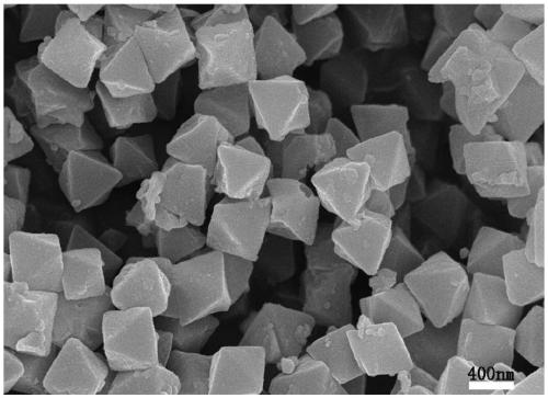
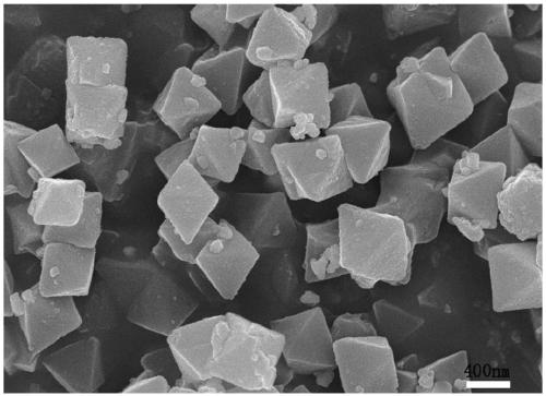
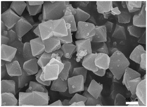
[0035] Depend on figure 1 , 2 , 3. It can be seen that the synthesized Uio-66 has a regular octahedral structure, and ...


PUM


Abstract

The invention provides a preparation method for a compound visible light catalyst. The method comprises the following steps: weighting P and AgNO3 at the mole ratio of elementary substance P to AgNO3 of 1:3; weighting ZrCl4 at the mole ratio of Zr4+ to Ag+ of (1-10):1; weighting terephthalic acid at the mole ratio of terephthalic acid to ZrCl4 of (1-1.2):1; dispersing the raw materials into a N,N-dimethyl formamide solvent, and then adding acetic acid, controlling reaction temperature at 160-180 DEG C and reacting for 20-24h, thereby compounding the Ag3PO4 / Uio-66 compound visible light catalyst. The preparation method provided by the invention is simple; the cost is low; compared with pure Ag3PO4, the compound visible light catalyst has a better photocatalysis effect; under the irradiation of visible light, 20mg / L rhodamine B solution can be almost completely degraded within 21min.

Description

technical field [0001] The invention belongs to the field of materials science and relates to a photocatalyst, in particular to an Ag catalyst which is easy to synthesize and has high catalytic efficiency. 3 PO 4 / Uio-66 composite visible light catalyst preparation method. Background technique [0002] Solar energy is a kind of abundant, clean and infinitely usable energy, which has a very broad application prospect. Solar photocatalysis is an important way to utilize solar energy, including energy photocatalysis and environmental photocatalysis. Among them, environmental photocatalysis refers to the photocatalytic reaction of photocatalysts under light irradiation, so as to achieve the purpose of decomposing various pollutants and killing bacteria and viruses. Currently the most common photocatalyst is TiO 2 , however, TiO 2 As a photocatalyst, there are two problems, one is TiO 2 The bandgap width is wide, 3.2eV, which leads to a narrow photoresponse range, and can o...

Claims


Application Information

Patent Timeline
Patent Type & Authority Patents(China)
IPC IPC(8): B01J31/26C02F1/30C02F101/30
CPCB01J31/26B01J35/004C02F1/30C02F2101/30C02F2305/10
Inventor 张娜张小磊房永征甘传先刘静慧胡毓宁
Owner SHANGHAI SUPERHIGH ENVIRONMENTAL PROTECTION TECH CO LTD
Why Eureka
Try Eureka