Aluminum alloy part surface paint removing treatment device and method

A technology for aluminum alloy parts and processing devices, which is applied in the field of paint removal treatment, can solve the problems of no application in the aircraft industry, and achieve the best paint removal effect, fast paint removal speed, and high paint removal efficiency

Inactive Publication Date: 2017-08-11
陕西汇智达清光电科技有限公司
View PDF7 Cites 5 Cited by
  • Summary
  • Abstract
  • Description
  • Claims
  • Application Information

AI Technical Summary

Problems solved by technology

In recent years, a variety of laser cleaning machines have been launched in China, b...

Method used


Image

  • Aluminum alloy part surface paint removing treatment device and method
  • Aluminum alloy part surface paint removing treatment device and method

Examples


Embodiment 1

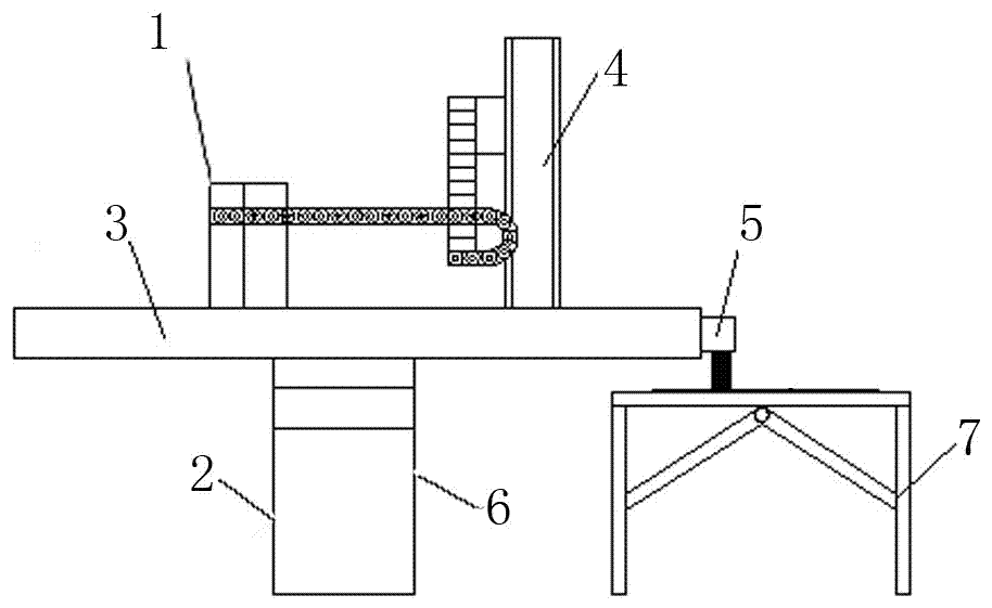
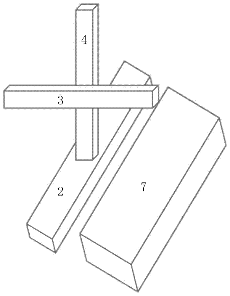
[0033] The surface paint removal treatment device for aluminum alloy parts of the present invention includes a workbench 7, a three-dimensional truss 6, a laser, a laser scanning device 5 and a control system 1, wherein the three-dimensional truss 6 includes an X-axis truss 2, a Y-axis truss 3 and a Z-axis truss. The axis truss 4; the workbench 7 is set parallel to the horizontal plane, and the X-axis truss 2 is set on the same level parallel to the workbench 7, wherein the X-axis truss 2 is located at the bottom of the entire three-dimensional truss 6, and its top is provided along the X-axis direction. Z-axis truss 4 slides in the chute on the top of X-axis truss 2; Y-axis truss 3 is connected to Z-axis truss 4 through a slider, wherein the slider slides along the Z-axis direction, and the Y-axis truss moves along the Y-axis The direction is connected with the sliding block; the laser is fixed on the Y-axis truss 3, and the laser scanning device 5 is fixed on the laser outlet...

Embodiment 2

[0041] This embodiment also includes a dust remover 3 connected to the control system 1, the dust remover 3 is provided with two air suction pipes, both of which are arranged on the Y-axis truss 3, and are respectively symmetrically arranged on the laser scanning device 5 The distance between the air suction port of the dust remover 3 and the focusing plane of the laser in the laser is 30-50mm. In this embodiment, when the laser is started, the control system 1 starts the dust remover, and the suction port of the dust remover moves with the laser, 30-50mm. This distance can effectively suck away the smoke and paint flake dust produced by laser paint removal in time, and can prevent The smoke and dust pollution field mirror absorbs the smoke and particles generated during the paint removal process simultaneously, and is filtered and collected by the dust collector to achieve pollution-free operation, thereby achieving the purpose of clean production and green manufacturing.

Embodiment 3

[0043] This embodiment is basically the same as Embodiment 1 or 2, except that this embodiment also includes a water-cooling device connected to the control system 1, the water-cooling device includes a refrigerator and a circulation pipe loop, and the circulation pipe loops are respectively sleeved External to the laser and control system 1.

[0044] In this embodiment, the circulation pipe circuit of the water cooling device is used to cool the laser and the control system 1 to avoid equipment damage due to excessive temperature.


PUM


Abstract

The invention relates to a method and a device for performing paint stripping treatment on the surface of an aluminum alloy part by using laser technology. The surface paint removal treatment device for aluminum alloy parts of the present invention includes a workbench, a three-dimensional truss, a laser, a laser scanning device and a control system, wherein the three-dimensional truss includes an X-axis truss, a Y-axis truss, and a Z-axis truss; the workbench is parallel to the Horizontal plane setting, the X-axis truss is set parallel to the workbench on the same level, wherein the X-axis truss is located at the bottom of the entire three-dimensional truss, and its top is provided with a chute extending along the X-axis direction; the Z-axis truss is movable on the X-axis truss In the chute on the top; the Y-axis truss is movably arranged on the Z-axis truss, which can slide along the Z-axis and the Y-axis respectively. The surface paint removal treatment device for aluminum alloy parts of the present invention, the control system can adjust the laser parameters in the laser and the movement track and running speed of the three-dimensional truss according to different paint layer combinations, so that the paint layer can be removed accurately and efficiently without damaging the substrate .

Description

technical field [0001] The invention relates to a method and a device for performing paint stripping treatment on the surface of an aluminum alloy part by using laser technology. Background technique [0002] The use of aluminum alloy can be seen everywhere in real life, especially most of the parts on the aircraft are made of aluminum alloy. However, when an aircraft is in use for about 4 years, it needs to undergo a D inspection and overhaul once. During the overhaul, it is necessary to remove all the paint layers on the skin surface of the whole machine and most of the key parts. This is not only for repainting after the overhaul to obtain a brand new protective decorative coating, but also for detecting Or the defects and fatigue cracks of structural parts, so as to avoid fatigue damage accidents of aircraft. In the process of aircraft manufacturing, it is often encountered that parts need to be removed for repair. [0003] At present, the paint removal of domestic ai...

Claims


Application Information

Patent Timeline
IPC IPC(8): B23K26/354B23K26/08
CPCB23K26/354B23K26/0884
Inventor 赵明海纪大满王文全关军张刚谢佳宏
Owner 陕西汇智达清光电科技有限公司
Why Eureka
Try Eureka