Brillouin optical fiber sensing system and method

An optical fiber sensing system and optical fiber sensing technology, applied in the direction of using optical devices to transmit sensing components, can solve the problems of limited application of BOTDA system, short sensing distance, large measurement error, etc., to reduce non-localization. Domain effect, improved signal-to-noise ratio, and the effect of increased measurement accuracy

Inactive Publication Date: 2014-07-09
GUANGXI NORMAL UNIV
View PDF5 Cites 25 Cited by
  • Summary
  • Abstract
  • Description
  • Claims
  • Application Information

AI Technical Summary

Problems solved by technology

[0003] Limited by the phonon lifetime of 10ns, the best spatial resolution of the traditional direct detection BOTDA system is 1m. In addition, due to the existence of fiber nonlinear effects, the sensing length of traditional BOTDA is limited by the maximum optical power allowed by the pump pulse light. And due to the limitation of the non-local effect caused by the power loss of the pump pulse, these shortcomings greatly limit the application of the BOTDA system
In order to improve the spatial resolution of the system, people proposed the method of differential pulse pair, but this method needs twice the measurement time. For this reason, people also proposed the scheme of optical path difference, that is, injecting pulses with different pulse widths in the optical domain at the same time. The Stokes pump light and the anti-Stokes pump light are used to subtract the Brillouin gain and Brillouin loss brought about by their interaction with the probe light at the same time, and finally measure the optical power of the probe light over time However, because the Brillouin gain signal after the optical path difference is relatively weak, the sensing distance is not long and the measurement error is relatively large. In addition, the non-local effect caused by the mismatch and loss of the optical power of the two pump pulses is also will cause systematic errors in the measurement

Method used


Image

  • Brillouin optical fiber sensing system and method
  • Brillouin optical fiber sensing system and method

Examples


Embodiment Construction

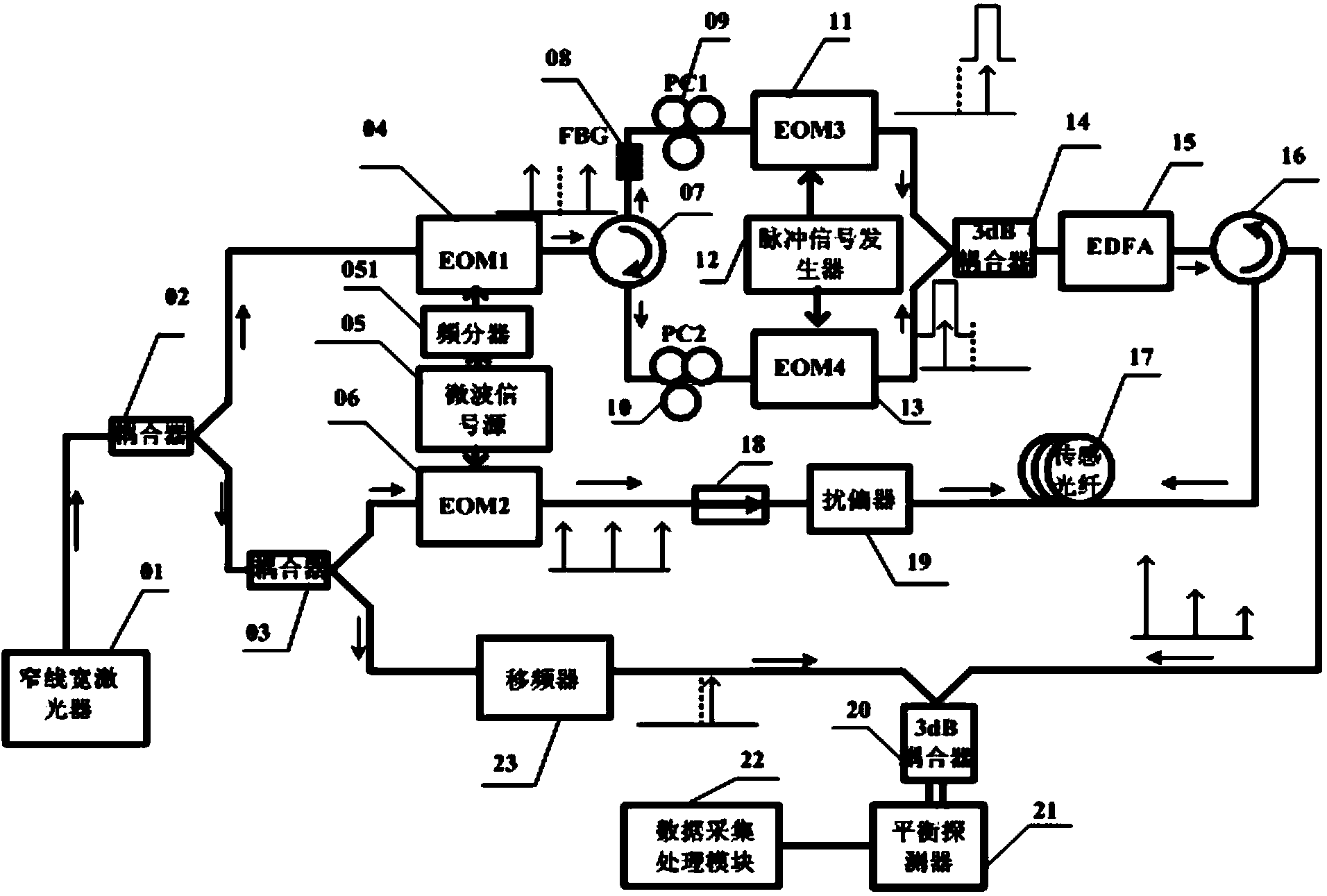
[0026] A Brillouin optical fiber sensing system, such as figure 1 As shown, there are mainly a narrow linewidth laser 01, a first coupler 02, a second coupler 03, a first electro-optic modulator 04, a second electro-optic modulator 06, a third electro-optic modulator 11, and a fourth electro-optic modulator 13 , Microwave signal source 05, frequency divider 051, first optical circulator 07, second optical circulator 16, FBG filter 08, first polarization controller 09, second polarization controller 10, pulse signal generator 12, Erbium-doped fiber amplifier 15, sensing fiber 17, first 3dB coupler 14, second 3dB coupler 20, isolator 18, scrambler 19, frequency shifter 23, balanced photodetector 21, and data acquisition and processing module 22 composition.

[0027] The output end of the narrow linewidth laser 01 is connected to the input end of the first coupler 02, and the two output ends of the first coupler 02 are respectively connected to the input end of the first electro-opt...


PUM


Abstract

The invention discloses a Brillouin optical fiber sensing system and method. A light difference parameter amplifying technology, a three-frequency probe laser technology and a coherent detection technology are adopted at the same time. By means of the light difference parameter amplifying technology, the spatial resolution of the Brillouin optical fiber sensing system can be improved to a sub-meter grade, the coherent detection technology can improve the signal to noise ratio and measurement precision of the system and increase the sensing distance, and the three-frequency probe laser technology compensates power loss of two beams of pump pulse light, can greatly reduce the non-local effect brought by power mismatch of the two beams of the pump pulse light and loss in long-distance sensing, and further improves measurement precision, so that it is guaranteed that the Brillouin optical fiber sensing system has a relatively long sensing distance, and the sub-meter spatial resolution and high measurement precision can be achieved.

Description

Technical field [0001] The invention relates to the technical field of optical fiber sensing, in particular to a Brillouin optical fiber sensing system and method. Background technique [0002] When the frequency difference of the two light waves propagating in opposite directions in the fiber is within the inherent Brillouin gain range of the fiber, the two light beams undergo stimulated Brillouin effect through the acoustic wave field, and energy transfer occurs between the two beams. When the frequency difference of the light is equal to the inherent Brillouin frequency shift (BFS) of the fiber, the energy transfer amount is the largest. Based on this, the Brillouin frequency shift distribution along the length of the fiber can be measured. Brillouin Optical Time Domain Analysis (BOTDA) technology It is based on the above principle and the linear relationship between Brillouin frequency shift (BFS) and temperature and strain to realize distributed temperature and strain sensin...

Claims


Application Information

Patent Timeline
Patent Type & Authority Applications(China)
IPC IPC(8): G01D5/353
Inventor 胡君辉阳丽潘福东王力虎
Owner GUANGXI NORMAL UNIV
Why Eureka
Try Eureka