
Optoelectronic oscillator based on intermediate frequency selection

A photoelectric oscillator and intermediate frequency technology, applied in lasers, laser components, semiconductor lasers, etc., can solve the problems of not considering the phase noise of the local oscillator signal, no link transmission relationship research, multi-ring OEOQ value reduction, etc., to achieve a large Cost advantage, phase noise reduction, and high Q effect

Active Publication Date: 2017-08-11
ZHEJIANG UNIV
View PDF10 Cites 20 Cited by
  • Summary
  • Abstract
  • Description
  • Claims
  • Application Information

AI Technical Summary

Problems solved by technology

However, the overall Q value of multi-ring OEO is the average value of long-ring OEO and short-ring OEO. Compared with single long-ring OEO, the Q value of multi-ring OEO will decrease and the phase noise will increase.
[0005] In the article "RF-Down and RF-Up converting Optoelectronic Oscillator for Spurious Suppression" (Ieice Technical Report Microwaves 2012, Volume 112, Page 5-10) published by Mizuma M et al., the OEO scheme of frequency up-down conversion is proposed to improve the side-mode suppression ratio In this scheme, the local oscillator signal and the oscillation signal are first down-converted to the center frequency of the intermediate frequency band-pass filter, and then up-converted back to the OEO oscillation frequency through a narrow-band intermediate frequency filter. By using a narrow-band intermediate frequency filter It is easy to suppress the side mode and reduce the phase noise of the loop. However, it does not consider the influence of the phase noise of the local oscillator signal, and does not study the transmission relationship of the link.

Method used


Image

  • Optoelectronic oscillator based on intermediate frequency selection
  • Optoelectronic oscillator based on intermediate frequency selection
  • Optoelectronic oscillator based on intermediate frequency selection

Examples


Embodiment Construction

[0050] In order to describe the present invention more specifically, the technical solutions of the present invention will be described in detail below in conjunction with the accompanying drawings and embodiments.

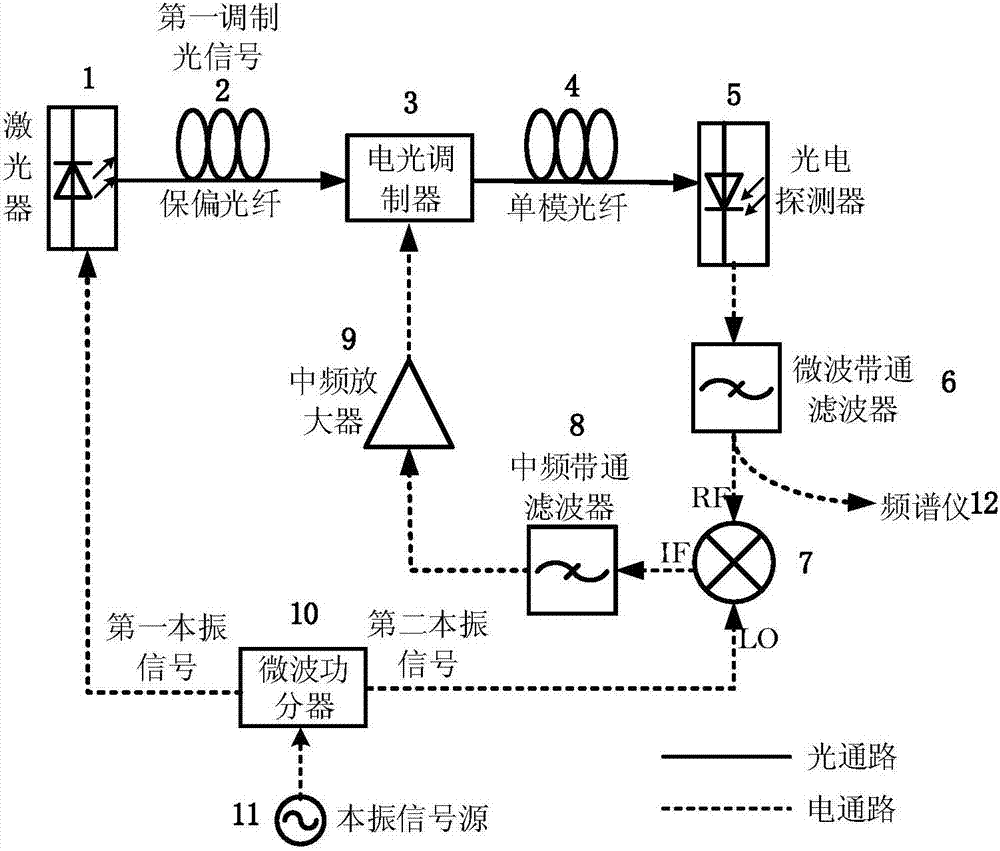
[0051] Such as figure 1 As shown, the optoelectronic oscillator based on intermediate frequency selection includes: local oscillator signal source 11, microwave power divider 10, laser 1, polarization maintaining fiber 2, electro-optic modulator 3, single-mode fiber 4, photodetector 5, microwave band Pass filter 6, mixer 7, intermediate frequency bandpass filter 8, intermediate frequency amplifier 9.

[0052] Laser 1 is a directly modulated distributed feedback laser or a vertical resonator surface emitting laser with narrow linewidth and high power, low relative intensity noise and good ability to resist environmental interference.

[0053] Increasing the output power of the laser can increase the transmission power in the system loop, which is beneficial to red...


PUM

PropertyMeasurementUnit
Poweraaaaaaaaaa

Abstract

The invention discloses an optoelectronic oscillator based on intermediate frequency selection. The optoelectronic oscillator comprises a local oscillator signal source, a microwave power divider, a laser, a polarization maintaining fiber, a single-mode fiber, an electro-optic modulator, a photoelectric detector, a microwave band-pass filter, a frequency mixer, an intermediate frequency band-pass filter and an intermediate frequency amplifier. Through up-conversion and down-conversion, side mode suppression of an OEO is realized through a narrowband intermediate frequency band-pass filter, so that an OEO loop is allowed to be longer to realize high Q value; and through matching of the polarization maintaining fiber in corresponding length and group delay of the intermediate frequency band-pass filter, influence of phase noise of a local oscillator signal is eliminated. The up-conversion in an OEO structure is realized through a microwave photon link; advantages of wide bandwidth and small insertion loss are realized; and frequency conversion loss can be reduced obviously by improving laser power.

Description

technical field [0001] The invention belongs to the technical field of photoelectric oscillators, in particular to a photoelectric oscillator based on intermediate frequency selection. Background technique [0002] Oscillators are key devices in electronic systems such as communication systems, navigation, radar, test instruments, and electronic countermeasures. Their phase noise performance often directly determines the performance of an electronic system. Oscillators can provide clock signals for high-speed digital systems, as local oscillator signals to achieve up- and down-conversion, and as reference sources in synchronous systems. These applications all place high requirements on the phase noise indicators of oscillators. The development of modern communication technology towards high bandwidth and high frequency has further increased the requirements for the performance of microwave oscillators. In the 1990s, a new type of microwave oscillator (optoelectronic oscilla...

Claims


Application Information

Patent Timeline
IPC IPC(8): H01S5/065G02F1/01
CPCG02F1/0121H01S5/0656H01S5/0657
Inventor 郭姣姣祝艳宏金晓峰余显斌金向东章献民池灏郑史烈
Owner ZHEJIANG UNIV
Learn More