Manufacturing method of vehicle components, as well as vehicle components and vehicle

A technology for parts and vehicles, applied in the field of vehicle parts and vehicles, manufacturing vehicle parts, can solve the problems of low mechanical properties and difficult molding

Active Publication Date: 2017-08-18
BEIJING AUTOMOTIVE IND CORP +1
View PDF7 Cites 13 Cited by
  • Summary
  • Abstract
  • Description
  • Claims
  • Application Information

AI Technical Summary

Problems solved by technology

[0004] The purpose of the present disclosure is to provide a method for manufacturing vehicle parts and vehicle parts and vehicles. The method is a revolutionary innovation to the traditional low-pressure injection molding process. The prepared parts can meet the requirements of mechanical properties and formability at the same time. It solves the problems of difficult forming of traditional lamination process and low mechanical performance of traditional injection molding process

Method used


Image

  • Manufacturing method of vehicle components, as well as vehicle components and vehicle
  • Manufacturing method of vehicle components, as well as vehicle components and vehicle
  • Manufacturing method of vehicle components, as well as vehicle components and vehicle

Examples


Embodiment 1

[0063] This embodiment is used to illustrate the method of manufacturing vehicle parts of the present disclosure.

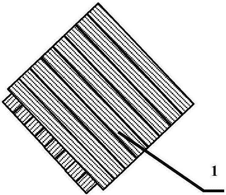
[0064] Lay up the biaxial cloth (purchased from Kefanle Special Textile Co., Ltd., made of T700 carbon fiber, the product number is BX300), the laying angle of the biaxial cloth layer is 90°, two adjacent layers of biaxial The laying angle of the cloth is 0°, and the number of layers is 13, such as figure 1 Laminate structure 1 shown. Nylon 6 resin (purchased from China Petrochemical Corporation, product number BL2340-H, melting point 220°C) was stretched to obtain a nylon 6 resin film, and the resin film was laid on the bottom of the laminated structure 1, according to The requirements of the target vehicle parts for the required prefabricated body structure are simulated by the FiberSim analysis software to obtain the cut shape, and then the laminated structure covered with the resin film is pre-cut by laser equipment to obtain the fiber prefabricated body 3, ...

Embodiment 2

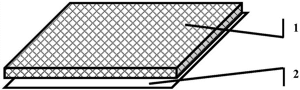
[0069] Manufacture vehicle components according to the method of embodiment 1, the difference is that the lay-up structure in the present embodiment adopts such as figure 2 The woven fabric shown (purchased from Toray Company, made of T700 carbon fiber, product number CK6244) is laminated. The laying angle of two adjacent layers of woven fabric is 90°, and the number of layers of the laminated structure is 19 layers.

Embodiment 3

[0071] Manufacture vehicle parts according to the method for embodiment 1, the difference is that the thermoplastic resin in the resin film and the injection molding compound in the present embodiment is polypropylene resin (purchased from China Petrochemical Corporation, commodity number is PPB-M02, fusing point is 170°C), the injection molding temperature is 220°C.


PUM


Abstract

The invention relates to manufacturing method of vehicle components, as well as vehicle components and a vehicle. The method comprises the following steps of: a, layering continuous-filament woven fabric to obtain a layering structure (1); b, laying a resin film (2) at the bottom of the layering structure (1), and then performing pre-cutting to obtain a fibrous preform (3); and c, placing the fibrous preform (3) in an injection mold with an injection molding space (8), after mold clamping, injecting an injection molding material (6) containing discontinuous fibers and thermoplastic resin into the injection mold, so that the injection molding space (8) is full of the injection molding material (6) through injection molding and the fibrous preform (3) is infiltrated with the injection molding material (6), and performing pressure maintaining and forming so as to obtain the vehicle components (7). The method belongs to revolutionary innovation of a conventional low-pressure injection molding process. The manufactured components can meet the requirements of mechanical properties and formability at the same time. The problems of difficult forming by the conventional laminating process and low mechanical performance of the conventional injection molding process are solved.

Description

technical field [0001] The present disclosure relates to the technical field of composite materials, and in particular, relates to a method for manufacturing vehicle parts, the vehicle parts and the vehicle. Background technique [0002] With the increasingly prominent energy crisis and environmental crisis, automobile lightweight has become an inevitable choice for the development of the automobile industry. Fiber-reinforced composite materials have the advantages of high specific strength and specific modulus, high temperature resistance, good fatigue resistance, and strong designability, and have been widely used in the aerospace field. However, due to the backward molding process and immature structural design technology, fiber reinforced composites have not been widely used in the automotive industry. Existing fiber-reinforced composite molding methods mainly include hand lay-up molding, winding molding, pultrusion molding, compression molding, bag compression molding,...

Claims


Application Information

Patent Timeline
Patent Type & Authority Applications(China)
IPC IPC(8): B29C70/36B29L31/30
Inventor 段瑛涛
Owner BEIJING AUTOMOTIVE IND CORP
Why Eureka
Try Eureka