Waste heat recovery biomass steam generator

A steam generator and waste heat recovery technology, which is applied in steam generation, steam boilers, steam boiler accessories, etc., can solve the problems of insufficient heat, unreasonable structure, and high exhaust temperature at the exhaust port, and achieve the effect of enhancing heat transfer. Improve the heat utilization rate and improve the effect of heat utilization rate

Active Publication Date: 2017-08-18
黄山容宇五金制品有限公司
View PDF6 Cites 8 Cited by
  • Summary
  • Abstract
  • Description
  • Claims
  • Application Information

AI Technical Summary

Problems solved by technology

Under such circumstances, on the one hand, the heat in the flue gas has not been fully transferred, resulting in excessively high exhaust gas temperature at the exhaust port and a great potential safety hazard.
On the other hand, the heat absorbed by the water in the water tank is insufficient and slow, resulting in low steam production efficiency
Even in the boiling state, the water movement in the water tank is mainly concentrated in the vertical direction, while the horizontal movement only exists in the upper and lower layers of the water tank, and there is basically no horizontal movement in the middle of the water tank, resulting in a low heat utilization rate
In addition, the biomass steam generators in the prior art generally have problems such as unreasonable structure and excessive volume.

Method used


Image

  • Waste heat recovery biomass steam generator
  • Waste heat recovery biomass steam generator
  • Waste heat recovery biomass steam generator

Examples


Embodiment Construction

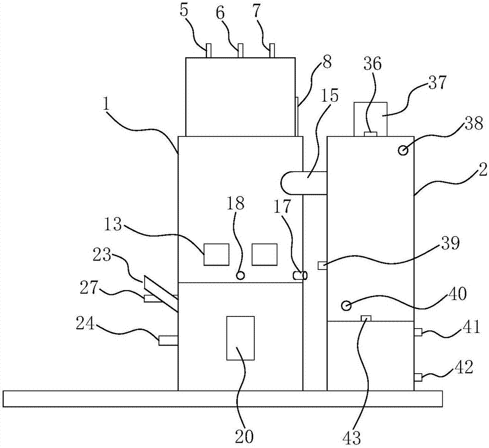
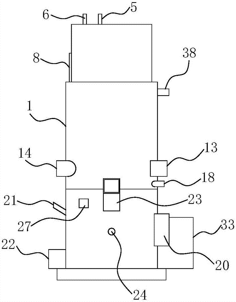
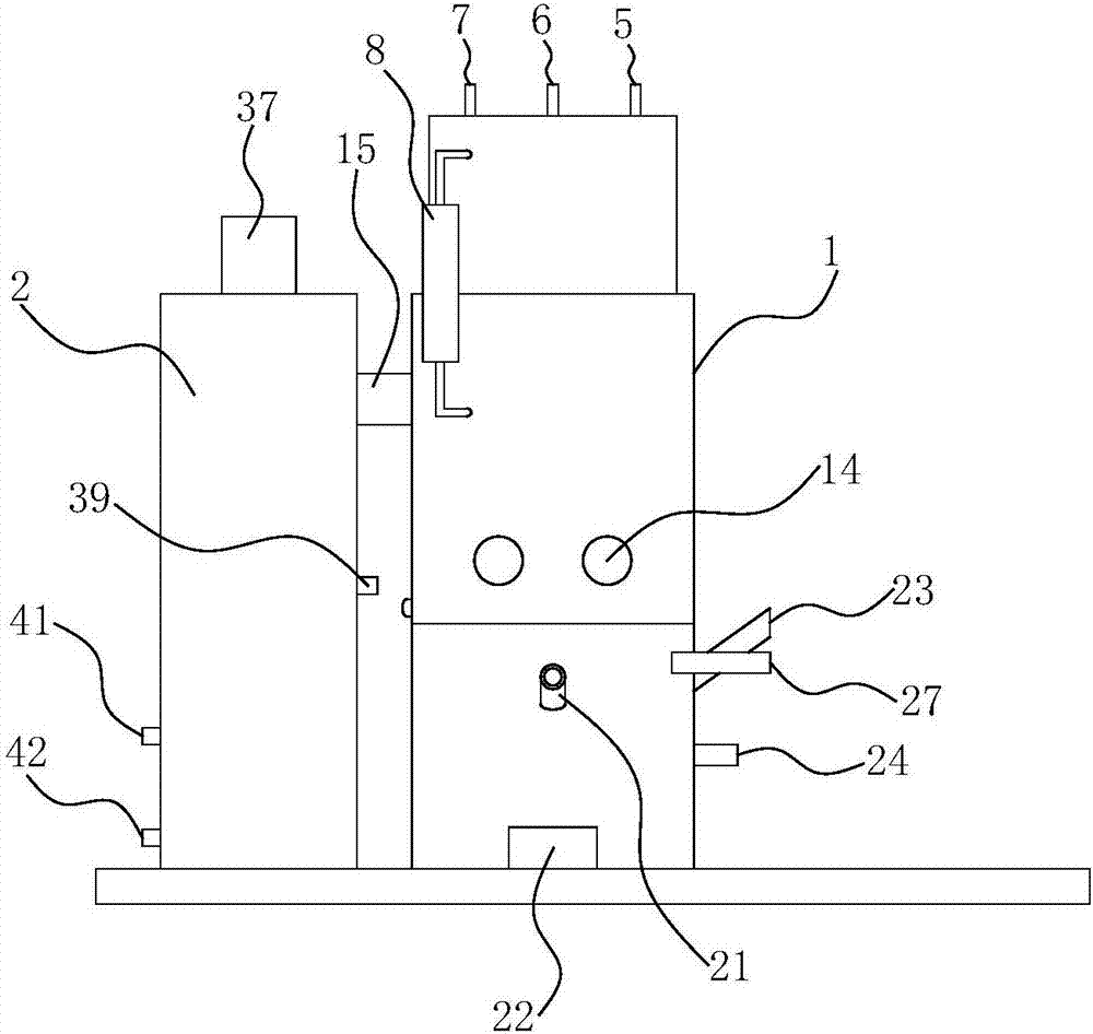
[0034] combine Figure 1-16 The waste heat recovery biomass steam generator shown includes a steam generator main body 1 and a waste heat recovery device 2 located on one side of the main body 1 . The waste heat recovery device 2 can be a commercially available conventional waste heat recovery device 2 . The waste heat recovery device 2 recovers waste heat from the flue gas passing through the main body 1, which makes the present invention more environmentally friendly and energy-saving, and at the same time can reduce the temperature of exhaust gas emission, greatly reducing the risk factor. The hot water produced after waste heat recovery can be directly used as domestic water, which is convenient to use. like Image 6As shown, the main body 1 includes a water exchange tank 3 on the upper part and a combustion chamber 4 on the lower part. The water exchange tank 3 is used as a place for heat exchange between high-temperature flue gas and water, and the combustion chamber 4 ...


PUM


Abstract

The invention belongs to steam generator equipment and aims to provide a waste heat recovery biomass steam generator which is extremely high in heat utilization ratio. The adopted technical scheme is that the waste heat recovery biomass steam generator comprises a steam generator body and a waste heat recoverer positioned on one side of the steam generator body, wherein the steam generator body comprises a heat exchange water tank positioned at the upper part and a combustion chamber positioned at the lower part; a first heat exchange mechanism is arranged in the heat exchange water tank and comprises an upper heat exchange box, a lower heat exchange box and a heat exchange fire tube set arranged between the upper heat exchange box and the lower heat exchange box; a flue gas inlet is formed in the bottom of the lower heat exchange box; and a first flow guide plate which is obliquely inclined downwards is arranged on the inner wall of the heat exchange water tank and spirally extends upwards along the inner wall of the heat exchange water tank. According to the waste heat recovery biomass steam generator, water movement in the heat exchange water tank can be promoted, and water at all parts of the heat exchange water tank can be subjected to full heat exchange with the first heat exchange mechanism, so that the heat utilization ratio and the steam preparation efficiency are greatly improved.

Description

technical field [0001] The invention belongs to steam generator equipment, in particular to a waste heat recovery biomass steam generator. Background technique [0002] A steam generator is a mechanical device that uses heat energy from fuel or other energy sources to heat water into steam, and is widely used in various occasions. For example: catering, sauna, etc., have brought great convenience to people's life. Biomass steam generator is a new type of steam generator that uses biomass energy as fuel. The biomass energy used is straw, sawdust, bagasse, rice bran, etc. In order to improve the heat utilization rate of the steam generator, some equipment in the prior art will also set up a waste heat recovery water tank in the rear section of the flue gas travel route, and make full use of the residual heat energy of the tail flue gas to recover the water in the waste heat recovery water tank. heating. The water in the waste heat recovery water tank can be directly used as...

Claims


Application Information

Patent Timeline
Patent Type & Authority Applications(China)
IPC IPC(8): F22B31/08F22B37/00
CPCF22B31/08F22B37/00
Inventor 王根勇胡新明张水利
Owner 黄山容宇五金制品有限公司
Why Eureka
Try Eureka