Unmanned aerial vehicle measuring instrument

A measuring instrument and unmanned aerial vehicle technology, which is applied in the field of unmanned aerial vehicle measuring instruments, can solve the difficulties in the normal laying out, positioning, pointing and other construction work of the laser pointing instrument, unevenness or other obstacles on the ground, and worker labor. In order to improve the efficiency of measurement and construction, reduce the labor intensity of workers and achieve the effect of compact structure

Inactive Publication Date: 2017-08-18
王玉振
View PDF0 Cites 0 Cited by
  • Summary
  • Abstract
  • Description
  • Claims
  • Application Information

AI Technical Summary

Problems solved by technology

However, in the actual production and construction process of the existing laser pointing instrument, the position and pointing of the instrument need to be manually adjusted.
In addition, based on the existing laser pointer, it needs to be fixedly installed on a fixed object. If the terrain is complex, that is, when the ground is uneven or there are other obstacles on the ground, it will give the laser pointer Normal laying out, positioning, pointing and other construction work will also cause certain difficulties

Method used


Image

  • Unmanned aerial vehicle measuring instrument
  • Unmanned aerial vehicle measuring instrument
  • Unmanned aerial vehicle measuring instrument

Examples


Embodiment 1

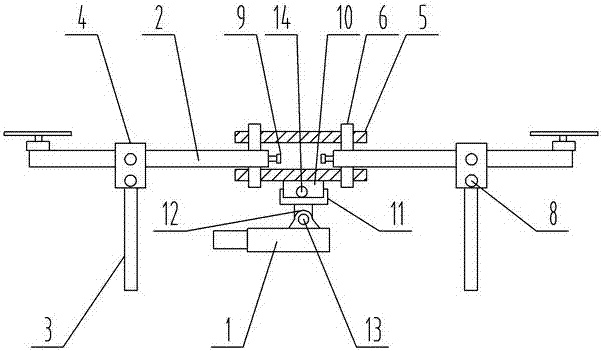
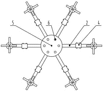
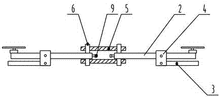
[0022] see Figure 1-4 , among the figures, the unmanned aerial vehicle surveying instrument of the present invention includes an unmanned aerial vehicle carrying a laser pointing instrument 1, and a PLC remote controller.

[0023] Among them, the UAV includes six arms 2 and six legs 3, as well as a driver, a card board assembly and a U-shaped splint 4 corresponding to the number of legs, wherein the card board assembly includes two cards arranged in parallel up and down. Plate 5, and pin shafts for fixedly connecting the upper and lower clamps, each support arm is distributed radially along the circumference of the clamps, and one end of the support arm is hinged between the upper and lower sides of the two clamps through the pin shaft 6, for connecting the upper and lower clamps The pin shaft of clamping plate is shared with the pin shaft of support arm and clamping plate hinge, and the top of each U-shaped splint is sheathed on each support arm continuously, and one end of ...


PUM


Abstract

The invention relates to an unmanned aerial vehicle measuring instrument. The unmanned aerial vehicle measuring instrument comprises an unmanned aerial vehicle carrying a laser orientation instrument and a PLC (Programmable Logic Controller) remote controller, wherein the unmanned aerial vehicle comprises a plurality of supporting arms and supporting legs, a driver, a clamping plate assembly and U-shaped clamping plates with the quantity corresponding to that of the supporting legs; the clamping plate assembly comprises upper and lower clamping plates and a fastening part for fixedly connecting the upper and lower clamping plates; the supporting arms are distributed in a radial shape along the periphery of the clamping plates; one end of each supporting arm is movably hinged between the two clamping plates; the upper parts of the U-shaped clamping plates sleeve the supporting arms in an interval or continuous manner; one end of each supporting leg is correspondingly and movably hinged into the lower parts of the U-shaped clamping plate; the laser orientation instrument is hung on the lower clamping plate through a snap fastener; the upper part of the snap fastener is fixedly connected with the lower clamping plate; the lower part of the snap fastener is rotatably connected with the laser orientation instrument through a swinging shaft and the swinging shaft is connected with a swinging motor; the swinging shaft is provided with a rotary angle potentiometer and a rotary speed potentiometer. The unmanned aerial vehicle measuring instrument integrates flexibility, convenience and practicability; the labor intensity is reduced and the measurement and construction efficiency is improved.

Description

technical field [0001] The invention belongs to the technical field of construction surveying, in particular to an unmanned aerial vehicle surveying instrument. Background technique [0002] ​The laser pointing device uses a low-power semiconductor laser to emit laser light, which is converged by an optical system to become a highly collimated laser beam, and the pointing work is completed through horizontal and vertical fine-tuning. However, in the actual production and construction process of the existing laser pointing device, the position and pointing of the device need to be adjusted manually. In addition, based on the existing laser pointer, it needs to be fixedly installed on a fixed object. If the terrain is complex, that is, when the ground is uneven or there are other obstacles on the ground, it will give the laser pointer Normal laying out, positioning, pointing and other construction work will also cause certain difficulties. Contents of the invention [0003...

Claims


Application Information

Patent Timeline
IPC IPC(8): G01C15/00B64C27/08B64C1/30B64D47/00
CPCG01C15/002B64C1/30B64C27/08B64D47/00B64U10/10B64U2101/00
Inventor 王玉振田方宋荣方王建华尹冬丽邱琳王雪平戴毓
Owner 王玉振
Why Eureka
Try Eureka