Modifying diaphragm for lithium-sulfur battery and preparation method thereof

A technology for lithium-sulfur batteries and diaphragms, which is applied in the field of modified diaphragms for lithium-sulfur batteries and its preparation. It can solve the problems of reducing the coulomb rate of lithium-sulfur batteries, reducing the utilization rate of active materials, and the capacity decay of lithium-sulfur batteries. Conductivity, improvement of electrochemical performance, effect of preventing dissolution

Active Publication Date: 2017-08-18
CHINA UNIV OF PETROLEUM (EAST CHINA)
View PDF5 Cites 18 Cited by
  • Summary
  • Abstract
  • Description
  • Claims
  • Application Information

AI Technical Summary

Problems solved by technology

The most serious of these is that the polysulfide anions formed during the charging and discharging process are easy to dissolve and diffuse in the organic electrolyte, and have side reactions with the positive electrode sulfur material and the negative electrode lithium sheet to form insulating precipitates (Li 2 S 2 and Li 2 S), on the one hand, this process reduces the Coulomb rate of lithium-sulfur batteries, and on the other hand, it also causes the loss of active materials, which leads to the rapid decline of lithium-sulfur battery capacity and greatly reduces the utilization rate of active materials.

Method used


Image

  • Modifying diaphragm for lithium-sulfur battery and preparation method thereof
  • Modifying diaphragm for lithium-sulfur battery and preparation method thereof
  • Modifying diaphragm for lithium-sulfur battery and preparation method thereof

Examples


Embodiment 1

[0027] (1) NH 2 -MIL-101(Al) was put into a tube furnace, and under the protection of nitrogen, the temperature was raised to 900°C at 10°C / min and kept for 5 hours. That is, NH carbonized at 900°C 2 -MIL-101(Al), marked NH 2 -MIL-101(Al)-900.

[0028] (2) NH 2 -MIL-101(Al)-900 and PVDF at a ratio of 9:1 and N-methylpyrrolidone are added to mix uniformly to obtain coating slurry; evenly coat the slurry on the surface of Celgard2400 diaphragm, and dry it in vacuum at 60°C for 12 hours. Modified septum, labeled NH 2 - MIL-101(Al)-900 modified diaphragm.

[0029] (3) Sulfur and carbon black are mixed and ball-milled at a mass ratio of 7:3, and the sulfur / carbon black after ball milling is placed in a tube furnace at 155° C. for 12 hours under a nitrogen atmosphere, and the above-mentioned sulfur / carbon black composite material is bonded with Add N-methylpyrrolidone at a mass ratio of 9:1 and mix evenly to obtain a coating slurry; coat the slurry evenly on the surface of alu...

Embodiment 2

[0032] NH in embodiment 1 (2) 2 -MIL-101(Al)-900 changed to NH 2 -MIL-101 (Al), the NH in the step (4) of embodiment 1 2 -MIL-101(Al)-900 modified diaphragm changed to NH2 -MIL-101 (Al) modified diaphragm, the others are the same as in Example 1.

Embodiment 3

[0034] With the NH in the step (4) of embodiment 1 2 -MIL-101 (Al)-900 modified diaphragm was changed to original diaphragm, and the others were the same as in Example 1.

[0035] results and analysis

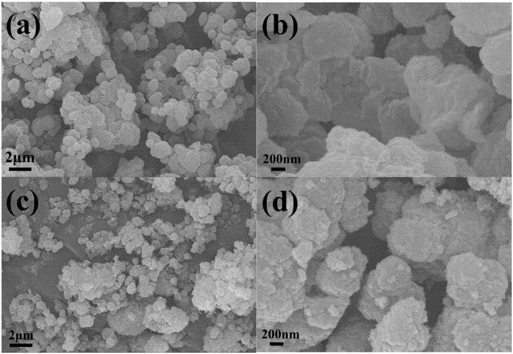
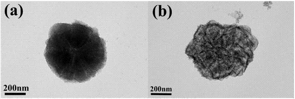
[0036] From figure 1 (a), (b) it can be seen that NH 2 -The shape of MIL-101(Al) is spherical and regular, figure 1 (c), (d) NH after carbonization at 900°C 2 -The morphology of MIL-101(Al)-900 remains basically unchanged, indicating that the skeleton structure of the material remains good after high-temperature carbonization.


PUM

PropertyMeasurementUnit
diameteraaaaaaaaaa
current efficiencyaaaaaaaaaa

Abstract

The invention provides a modifying diaphragm for a lithium-sulfur battery and a preparation method thereof. The modifying diaphragm is prepared by well mixing a carbonized LIL-101-series metal organic frame material with a binder and coating the surface of a diaphragm with a mixture, and metal cations have quite strong adsorption effect on polysulfide, so that dissolution of polysulfide is prevented, and shuttle effect is inhibited effectively. A carbonized porous skeleton structure has high lithium ion conductivity, plays a role as a current collector and is conducive to quick conduction of ions. The modifying diaphragm presents excellent circulating performance and rate performance when being used for the lithium-sulfur battery. The preparation method is simple, low in cost, environment-friendly and has good industrial application prospect.

Description

technical field [0001] The invention relates to the field of chemical power sources, in particular to a modified diaphragm for a lithium-sulfur battery and a preparation method thereof. Background technique [0002] The rapid rise of modern electric vehicles has put forward higher and higher requirements for the energy density of batteries. Now commercial lithium-ion batteries can no longer meet the application requirements of some electronic devices, and lithium-sulfur batteries, which have been increasingly researched in recent years, have high energy Density, its theoretical energy density reaches 2600Wh·kg -1 , which is 5 times that of commercial lithium batteries, meets the requirements of electric vehicles for batteries, and also meets the requirements of "light, small and thin" batteries for electronic portable devices. [0003] The lithium-sulfur battery is a secondary high-density energy battery system constructed with metal lithium as the negative electrode and el...

Claims


Application Information

Patent Timeline
Patent Type & Authority Applications(China)
IPC IPC(8): H01M2/14H01M2/16H01M10/052H01M50/403H01M50/431
CPCH01M10/052H01M50/40H01M50/409H01M50/403H01M50/411H01M50/449Y02E60/10
Inventor 李忠涛苏鑫邓深圳吴明铂吴文婷
Owner CHINA UNIV OF PETROLEUM (EAST CHINA)
Why Eureka
Try Eureka