Catalyst carrier and method for manufacturing same
A technology of catalyst carrier and manufacturing method, which is applied in the direction of catalyst carrier, catalyst activation/preparation, chemical instruments and methods, etc., which can solve the problems that high battery output power cannot be expected, and achieve the effect of high durability and high output power
- Summary
- Abstract
- Description
- Claims
- Application Information
AI Technical Summary
Problems solved by technology
Method used
Image
Examples
Embodiment 1
[0105] (Production of Carbon Particle B(1))
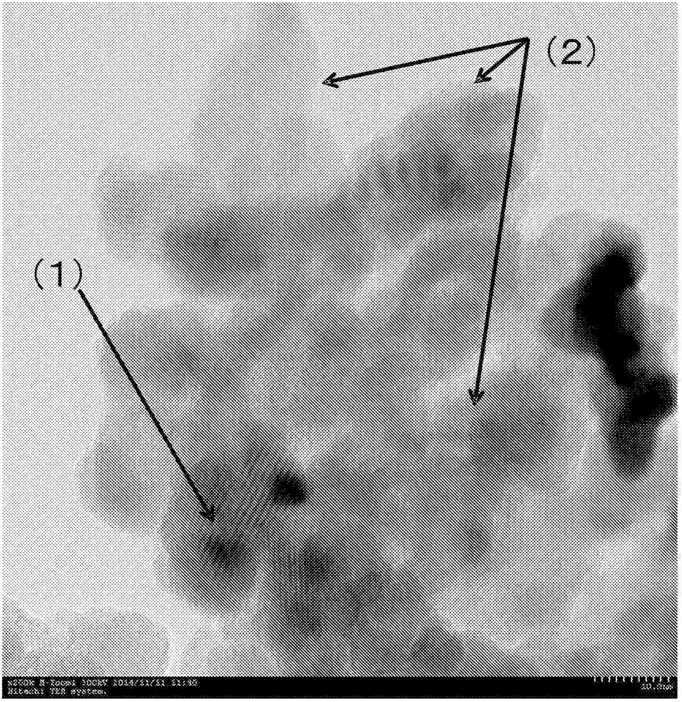
[0106] 5 g of titanium dioxide particles (anatase type, average particle size 7 nm, ST-01 manufactured by Ishihara Sangyo Co., Ltd.) and 5 g of polyvinyl alcohol powder (manufactured by Kanto Chemical Co., Ltd.) were uniformly mixed using a ball mill to obtain a solid mixed powder. This powder was put into a tubular furnace, heated to 700°C in an atmosphere of a mixed gas of hydrogen and nitrogen containing 4% by volume of hydrogen, and heat-treated at 700°C for 1 hour to obtain carbon particles wrapped with titanium dioxide particles. Oxide-carbon composite particles (hereinafter also referred to as "carbon particles B (1)"). The transmission electron microscope image of the carbon particle B(1) is shown in figure 1 . In the figure, (1) represents titanium dioxide particles, and (2) represents carbon in carbon particles B (1).
[0107] (Production of Catalyst Carrier)
[0108] Commercially available carbon material (BET specif...
Embodiment 2
[0136] Carbon particles B (1) were obtained in the same manner as in Example 1, and the carbon material (1) was mixed with the carbon particles B (1) to obtain a catalyst carrier (2). However, the ratio of the titanium dioxide particles to the total mass of the catalyst carrier (2) was 59% by mass.
[0137] Thereafter, platinum and cobalt were supported on the catalyst carrier (2) in the same manner as in Example 1, and heat treatment was performed to alloy the platinum and cobalt to obtain an electrode catalyst (2), and a fuel cell was fabricated and evaluated. The results are shown in Table 1.
Embodiment 3
[0139] Carbon particles B (1) were obtained in the same manner as in Example 1, and the carbon material (1) was mixed with the carbon particles B (1) to obtain a catalyst carrier (3). However, the ratio of the titanium dioxide particles to the total mass of the catalyst carrier (3) was 25% by mass.
[0140] Thereafter, platinum and cobalt were supported on the catalyst carrier (3) in the same manner as in Example 1, and heat treatment was performed to alloy the platinum and cobalt to obtain an electrode catalyst (3), and a fuel cell was fabricated and evaluated. The results are shown in Table 1.
PUM
| Property | Measurement | Unit |
|---|---|---|
| particle diameter | aaaaa | aaaaa |
| specific surface area | aaaaa | aaaaa |
| specific surface area | aaaaa | aaaaa |
Abstract
Description
Claims
Application Information
 - R&D
- Intellectual Property
- Life Sciences
- Materials
- Tech Scout
- Unparalleled Data Quality
- Higher Quality Content
- 60% Fewer Hallucinations
Browse by: Latest US Patents, China's latest patents, Technical Efficacy Thesaurus, Application Domain, Technology Topic, Popular Technical Reports.
© 2025 PatSnap. All rights reserved.Legal|Privacy policy|Modern Slavery Act Transparency Statement|Sitemap|About US| Contact US: help@patsnap.com


