
Anaerobic reactor

An anaerobic reactor and reactor technology, applied in the field of anaerobic reactors, can solve the problems of unfavorable industrial production efficiency and continuous stability, slow growth of microorganisms, low reactor load, etc., so as to reduce the concentration of wastewater to be treated and improve the biological The effect of quantity and efficient treatment

Active Publication Date: 2017-08-29
CHINA AGRI UNIV
View PDF7 Cites 6 Cited by
  • Summary
  • Abstract
  • Description
  • Claims
  • Application Information

AI Technical Summary

Problems solved by technology

High-concentration organic wastewater has a large degree of pollution to the environmental water body, and the treatment is difficult, which is one of the problems in the field of environmental protection research.
Anaerobic biological treatment technology has been widely used as an effective wastewater treatment method. However, the existing anaerobic biological process technology has the disadvantages of slow microbial growth and low microbial load, low reactor load and poor tolerance, which is not conducive to High efficiency and continuous stability of industrial production

Method used


Image

  • Anaerobic reactor
  • Anaerobic reactor
  • Anaerobic reactor

Examples


Embodiment 1

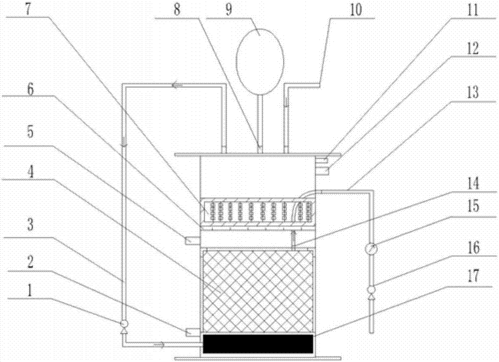
[0063] The anaerobic reactor of this embodiment has a rectangular parallelepiped structure with a total internal volume of 14L and an effective volume of 9L.

[0064] The internal temperature of the reactor is maintained at 35-37° C., and hot water is used for heat preservation. The hot water enters from the water inlet 2 of the water bath and is discharged from the water outlet 12 of the water bath.

[0065] The filler 23 is a cubic block sponge of 1.5×1.5 cm, and there are 160 fillers 23 in total, and the fixed filler bed 7 is located 8 cm above the flat membrane 4 . The liquid after dehydration by the cow farm screw extruder is used as the waste water to be treated, the COD concentration is 25-30g / L, and the total solid concentration is about 30g / L.

[0066] The filtration flux of the flat membrane 4 is 5-6L / h, and the transmembrane pressure difference is -4.5 to -5.8kPa.

[0067] The waste water enters the reactor through the feed port 10, and the amount of waste water ad...

Embodiment 2

[0075] The anaerobic reactor of this embodiment has a rectangular parallelepiped structure with a total internal volume of 14L and an effective volume of 9L.

[0076] The internal temperature of the reactor is maintained at 37-40° C., and hot water is used for heat preservation. The hot water enters from the water inlet 2 of the water bath and is discharged from the water outlet 12 of the water bath.

[0077] The packing 23 is a spherical carrier of 2 cm polypropylene material, and the fixed packing bed 7 is located 15 cm above the flat membrane 4 . The pig farm wastewater is used as the treatment object, the COD concentration is 10-20g / L, and the total solid concentration is about 20g / L.

[0078] The filtration flux of the membrane is 5-6L / h, and the pressure difference across the membrane is -4.0-5.0kPa.

[0079] Pig farm wastewater enters the reactor through the feed port 10, and the amount of wastewater added is 1.8 L, which is mixed with the inoculated sludge in the reac...


PUM


Abstract

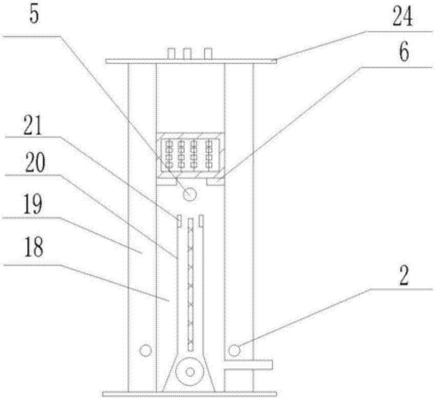
The invention belongs to the field of wastewater anaerobic fermentation, and in particular relates to an anaerobic reactor, the anaerobic reactor comprises a barrel body (18), a reactor cover (24), water bath sandwich layers (19), a fixed packing bed (7) and a plate film (4), the pair of water bath sandwich layers (19) are symmetrically arranged on both sides of the inner wall of a cylinder body (18), the plate film (4) is vertically arranged between the pair of water bath sandwich layers (19) in the cylinder body (18), both sides of the plate film (4) are provided with baffles (20) parallel to the plate film (4), the baffles (20) on both sides of the plate film (4) are respectively combined with the plate film (4) to form a space, a water outlet guide tube (13) and a film water outlet mouth (14) are connected, the water outlet guide tube (13) is provided with a liquid pump (16); a gas diffuser pipe(17) is arranged at the bottom of the cylinder body (18), an aeration loop (3) is arranged between the reactor cover (24 ) and the gas diffuser pipe (17), the aeration loop (3) is provided with an air pump (1); and the fixed packing bed (7) is arranged in the cylinder body (18) and above the plate film (4).

Description

technical field [0001] The invention belongs to the field of waste water anaerobic fermentation, in particular to an anaerobic reactor. Background technique [0002] With the deterioration of my country's water environment, higher requirements are put forward for the treatment of various wastewater. High-concentration organic wastewater has a large degree of pollution to the environmental water body, and the treatment is difficult, which is one of the problems in the field of environmental protection research. Anaerobic biological treatment technology has been widely used as an effective wastewater treatment method. However, the existing anaerobic biological process technology has the disadvantages of slow microbial growth and low microbial load, low reactor load and poor tolerance, which is not conducive to High efficiency and continuous stability of industrial production. Contents of the invention [0003] The purpose of the present invention is to provide an anaerobic...

Claims


Application Information

Patent Timeline
Patent Type & Authority Applications(China)
IPC IPC(8): C02F3/28C02F3/34C02F101/30
CPCC02F3/2866C02F3/34C02F2101/30C02F2203/006Y02E50/30
Inventor 乔玮董仁杰
Owner CHINA AGRI UNIV
Learn More