Integrated induction melting gas atomization powder manufacturing device and gas atomization powder manufacturing method

A pulverizing device and induction smelting technology, which is applied in the field of gas atomization pulverization, can solve problems such as difficulty in fine powder particle size, reduction of powder usability, unfavorable atmosphere control, etc., to achieve convenient acquisition, lower gas atomization pressure, Good powder making effect

Active Publication Date: 2017-09-01
HARBIN INST OF TECH SHENZHEN GRADUATE SCHOOL
View PDF8 Cites 8 Cited by
  • Summary
  • Abstract
  • Description
  • Claims
  • Application Information

AI Technical Summary

Problems solved by technology

[0004] At present, the smelting of traditional gas atomization powder making equipment is separated from the flow-limited pouring system, resulting in a certain contact with oxygen during the powder preparation process, which makes the prepared powder high in oxygen content or the easily oxidizable metal is completely oxidized, reducing the performance of the powder
There are also some gas atomization powder making equipment with integrated structure of smelting and pouring, but most of the equipment requires high vacuum, the structure is too complicated, the operation is troublesome, the maintenance is difficult, and the price is expensive. For gas atomization devices that do not require vacuum, The volume of the atomization chamber is generally large, which is not conducive to atmosphere control
At the same time, non-restricted atomizing nozzles are generally used in China at present, and it is difficult to make the powder particle size small. There are also some special nozzle designs, but the structure is relatively complicated.
In the gas atomization process, high-pressure gas is mostly used to spray the metal solution from the atomization chamber to form powder particles, and the nozzle is easy to block

Method used


Image

  • Integrated induction melting gas atomization powder manufacturing device and gas atomization powder manufacturing method
  • Integrated induction melting gas atomization powder manufacturing device and gas atomization powder manufacturing method
  • Integrated induction melting gas atomization powder manufacturing device and gas atomization powder manufacturing method

Examples


Embodiment 1

[0054] An integrated induction smelting gas atomization powder making device comprises an induction melting device and a gas atomization powder making device.

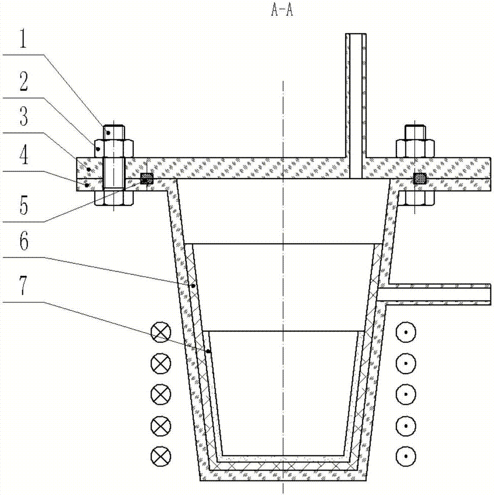
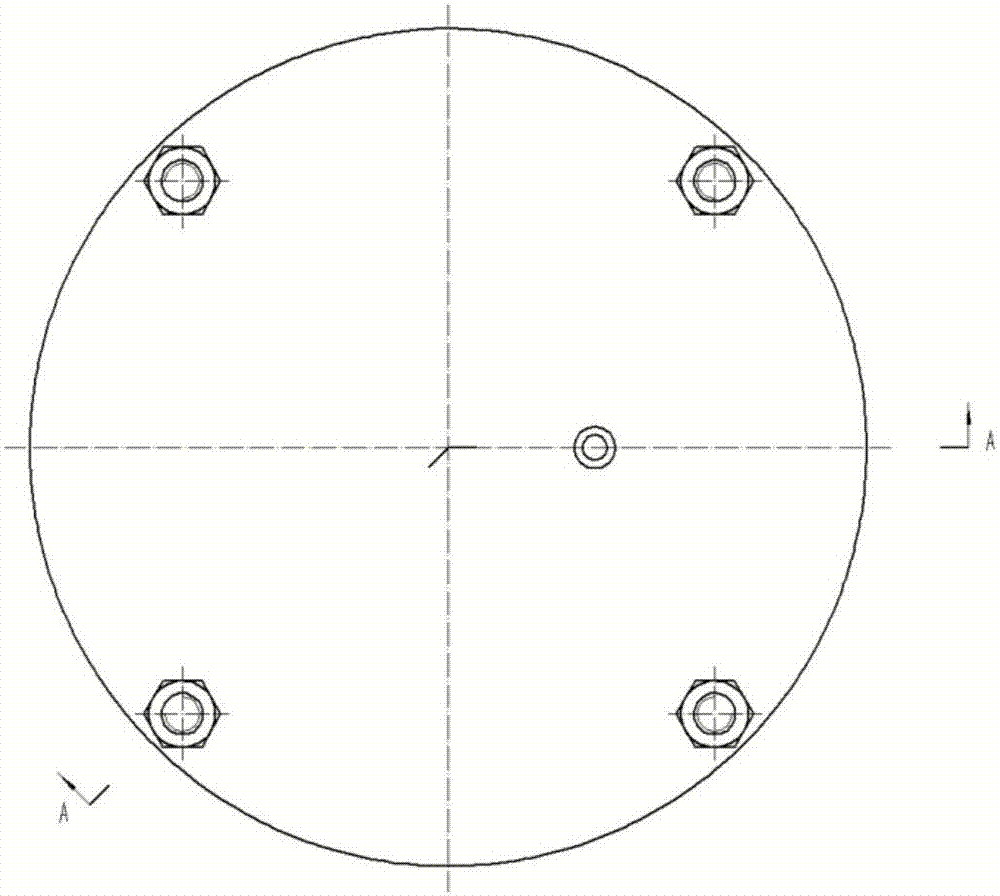
[0055] refer to Figure 1~Figure 2 , the induction melting device includes a melting quartz cup 4 and a melting quartz cover 3, both of which are sealed and assembled through an O-ring 5, a hexagonal bolt 1 and a hexagonal nut 2, and the melting crucible 7 is placed in the melting quartz cup 4, and the melting is carried out by silicic acid The aluminum cotton 6 is separated from the inner wall of the smelting quartz cup 4, and the outer wall of the smelting quartz cup 4 is coated with an induction coil to heat and melt the alloy.

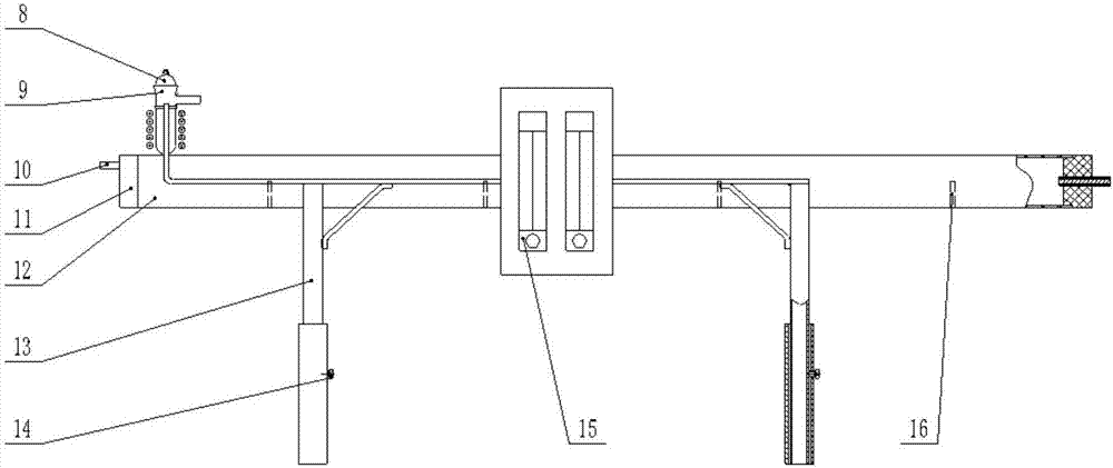
[0056] refer to Figure 3~Figure 5 , the gas atomization powder making device includes a support frame 13, the height of the support frame 13 is adjusted through the expansion and contraction of the internal steel pipe and with the screw 14; In the groove of the rack, it is used to collec...

Embodiment 2

[0066] The device and method of Example 1 were used to prepare Sn elemental metal powder. Cut pure Sn to within 10×10×20 mm size. Such as Figure 1~Figure 6 As shown, the following steps are taken:

[0067] Step S1: if Figure 1~Figure 6 As shown, unscrew the screw 14, adjust the height of the support frame 13, make the small hole opened in the quartz tube 12 closely contact with the nozzle 17 of the small gas atomization crucible 9, and rotate the solid silica gel plug 11 to make the porous corundum tube 10 empty Aim at the outlet of the nozzle 17 of the small gas atomization crucible 9, stick the solid silica gel plug 11 to the quartz tube 12 with adhesive tape, punch another hole and connect the solid silica gel plug 11 with an interference fit porous corundum tube in the hole Also taped to the quartz tube 12.

[0068] Step S2: Put a small piece of cut Sn in the gas atomization small crucible 9, cover the gas atomization small crucible cover 8, press it tightly with iro...

Embodiment 3

[0073] Adopt the device and method of embodiment 1 to carry out Cu-based Cu-Sn alloy powder preparation, as Figure 1~Figure 6 As shown, the following steps are taken:

[0074] Step S1: Put 39.1g of pure Cu and 60.9g of pure Sn in the smelting crucible 7, tighten the hexagonal nut 2, pass Ar gas into the smelting quartz cup 4, and pass through the gas outlet of the smelting quartz cup 4 and the outer water tank through four Fluorine tube connection to ensure better sealing. Turn on the induction heating equipment, turn off the induction heating equipment when the alloy is in a completely molten state and cool to a completely solidified state, repeat this three times, cool to room temperature, turn off the gas, take out the master alloy and cut it into a size of 10×10×20 mm.

[0075] Step S2: unscrew the screw 14, adjust the height of the support frame 13, make the small hole opened in the quartz tube 12 closely contact with the nozzle 17 of the small gas atomization crucible ...


PUM


Abstract

The invention provides an integrated induction melting gas atomization powder manufacturing device and a gas atomization powder manufacturing method. The integrated induction melting gas atomization powder manufacturing device comprises a gas atomization powder manufacturing device body. The gas atomization powder manufacturing device body comprises a supporting frame and a gas atomization crucible. A quarts tube used for collecting alloy powder is arranged on the supporting frame. One end of the quarts tube is connected with an alundum tube in which protective gas is led. The supporting frame is provided with an induction coil, and the gas atomization crucible is arranged in the induction coil. A nozzle is arranged at the bottom of the gas atomization crucible and faces the interior of the quarts tube. The axis of the nozzle of the gas atomization crucible is perpendicular to the axis of the quarts tube. An opening of the alundum tube faces the position of an outlet of the nozzle, and the opening end of the quarts tube is sealed through a stopper. The integrated induction melting gas atomization powder manufacturing device is simple in structure, small in occupied area and easy to assemble, the phenomenon that liquid blocks the nozzle cannot happen in the powder manufacturing process, meanwhile, the gas leading flow can be changed, and therefore the particle size distribution ratio of powder manufacturing is changed.

Description

technical field [0001] The invention relates to a gas atomization powder making equipment, in particular to an integrated induction smelting gas atomization powder making device and a gas atomization powder making method. Background technique [0002] Gas atomization powder making technology is the main method of producing metal and alloy powders. The principle of powder making is to use high-speed airflow to crush the liquid metal flow flowing out of the catheter tube into small droplets and solidify into powder during the subsequent flight. process. Gas atomized powder has the advantages of controllable powder particle size, low oxygen content, and is suitable for the production of various metal and alloy powders. It has become the main direction for the preparation of high-performance and special alloy powders. With the emergence of new powder metallurgy technology and new materials and the application of powder materials in chemical industry, electronic device preparati...

Claims


Application Information

Patent Timeline
Patent Type & Authority Applications(China)
IPC IPC(8): B22F9/08
CPCB22F9/082B22F2009/0836B22F2009/0844B22F2009/0888B22F2009/0892B22F2009/0896Y02P10/25
Inventor 计红军周均博梁孟陆骅俊马舒
Owner HARBIN INST OF TECH SHENZHEN GRADUATE SCHOOL
Why Eureka
Try Eureka