Partition cavity type small-sized rubbish pyrolysis and gasification incinerator

A pyrolysis gasification and combustion furnace technology, applied in the direction of incinerators, combustion methods, combustion types, etc., can solve the problems of high infrastructure construction and transshipment costs, high investment costs, and large processing capacity, and achieve simple structure and construction Effects of low cost and increased waste disposal volume

Pending Publication Date: 2017-09-01
重庆航天工业有限公司
View PDF9 Cites 10 Cited by
  • Summary
  • Abstract
  • Description
  • Claims
  • Application Information

AI Technical Summary

Problems solved by technology

The currently recognized best disposal method is centralized waste incineration for power generation, which has high investment costs and large processing capacity, and is generally used in large and medium-sized cities with large populations
For towns and vast rural areas with a small population and relatively low domestic waste production, long-distance transshipment is required, and the cost of infrastructure construction and transshipment is very high

Method used


Image

  • Partition cavity type small-sized rubbish pyrolysis and gasification incinerator
  • Partition cavity type small-sized rubbish pyrolysis and gasification incinerator
  • Partition cavity type small-sized rubbish pyrolysis and gasification incinerator

Examples


Embodiment Construction

[0026] Below by embodiment and in conjunction with accompanying drawing, the present invention will be further described:

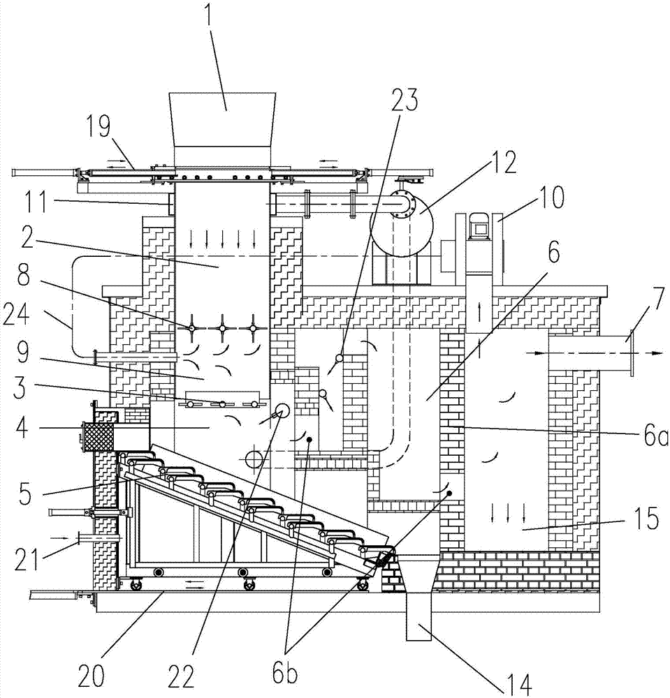
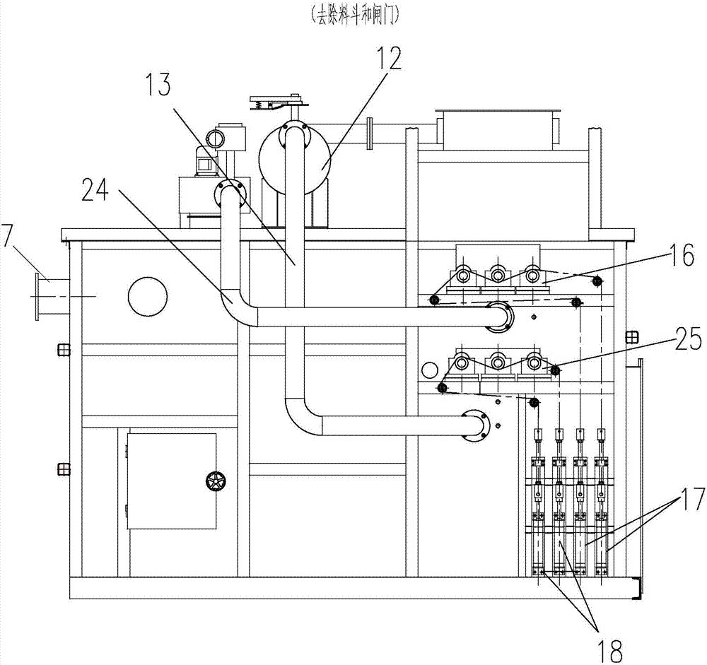
[0027] combine figure 1 , figure 2 As shown, a chamber-type small garbage pyrolysis gasification combustion furnace mainly consists of a hopper 1, a drying chamber 2, an upper grate 3, a combustion chamber 4, a lower grate 5, and a secondary combustion chamber arranged in the combustion furnace. Chamber 6 and smoke outlet 7 etc. are formed. The hopper 1, the drying chamber 2, the upper grate 3, the combustion furnace chamber 4, and the lower grate 5 are arranged sequentially from top to bottom.

[0028] The bottom of the hopper 1 is provided with a gate 19, and the gate 19 preferably adopts a double-open gate, consisting of a left gate and a right gate. After simple sorting (removing large garbage such as sofas, ironware, glass, etc.) contained in the domestic garbage, the garbage is transported to the hopper 1 on the top of the combustion furnace by ...


PUM


Abstract

The invention discloses a partition cavity type small-sized rubbish pyrolysis and gasification incinerator comprising a hopper, a gate, a drying cavity, an upper fire grate, a combustion hearth cavity, a lower fire grate and a secondary combustion chamber. High-temperature smoke in the secondary combustion chamber is guided into a pyrolysis gasification cavity. A part of high-temperature smoke flows upward into the drying cavity to dry rubbish, generated steam is guided into a condensation liquefying tank to be liquefied through a steam suction cavity, odor flows back into the combustion hearth cavity for high-temperature calcinations treatment, and smoke and the odor are prevented from escaping. The other part of high-temperature smoke flows downwards and is combined with heat generated by the combustion hearth cavity to form convection and radiation, rubbish is made to conduct pyrolysis and gasification at the same time, gasified gas flows out downwards from the upper fire grate to enter the combustion hearth cavity to be combusted, rubbish carbon overturned downwards by the upper fire grate is combusted on the lower fire grate, an opposite firing flame is formed between the upper fire grate and the lower fire grate, the gasified gas and pyrolyzed rubbish carbon form complementary combustion in the combustion hearth cavity, a durable high temperature keeping area enables dioxin type harmful matter to be decomposed, and heat energy generated by combustion is fully recycled.

Description

technical field [0001] The invention belongs to the field of garbage pyrolysis and gasification combustion furnaces (ie, incinerators), and in particular relates to a chamber-type small garbage pyrolysis gasification combustion furnace. Background technique [0002] With the improvement of people's living standards, more and more domestic garbage is produced in daily life, and the content of non-degradable components is also increasing, and the pollution to the environment is increasing day by day. The currently recognized best disposal method is centralized waste incineration for power generation, which has high investment costs and large processing capacity, and is generally used in large and medium-sized cities with large populations. For towns and vast rural areas with a small population and relatively low domestic waste production, long-distance transshipment is required, and the cost of infrastructure construction and transshipment is very high. [0003] Therefore, fo...

Claims


Application Information

Patent Timeline
Patent Type & Authority Applications(China)
IPC IPC(8): F23G5/027F23G5/04F23G5/16F23G5/44
CPCF23G5/0276F23G5/04F23G5/16F23G5/444F23G2205/14F23G2201/303F23G2202/103F23G2201/10
Inventor 万铁吾王征宇陈伟黄定伦
Owner 重庆航天工业有限公司
Why Eureka
Try Eureka