Nitridation controllable zero-pollution ion nitriding device
An ion nitriding, zero-pollution technology, applied in metal material coating process, coating, solid-state diffusion coating, etc., can solve the problems of non-adjustable anode-cathode spacing, uncontrollable nitriding, ammonia pollution, etc., to achieve Effects of zero-pollution ion nitriding, shortening production cycle, and solving pollution problems
- Summary
- Abstract
- Description
- Claims
- Application Information
AI Technical Summary
Problems solved by technology
Method used
Image

Examples
Embodiment Construction
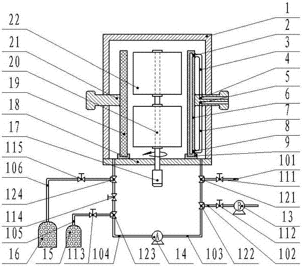
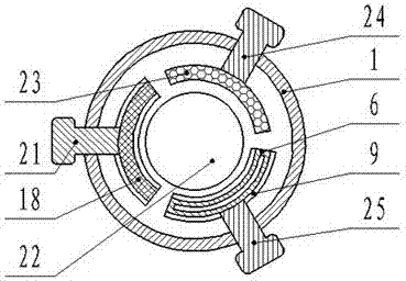
[0030] Such as figure 1 and figure 2 As shown, a zero-pollution ion nitriding device with controllable nitriding includes a furnace body 1, a furnace chassis 18, a transmission system, an adjustable cathode system, a rapid cooling system, an adjustable anode system, and a zero-pollution gas circulation system. The furnace body 1 is placed directly above the furnace chassis 18 to form a nitriding chamber, and the bottom of the nitriding chamber is provided with an air inlet and an air outlet; the transmission system is fixed in the middle of the furnace chassis 18; the adjustable cathode system, the rapid cooling system and the adjustable anode system are placed In the middle of the nitriding chamber; the zero-pollution gas circulation system is placed in the outer lower part of the furnace chassis 18.
[0031] The transmission system includes a counterclockwise motor 17, a cathode support 20, and a workpiece 22. The counterclockwise motor 17 is connected to the cathode suppo...
PUM
 Abstract
Description
Claims
Application Information