
Organic electroluminescent device, OLED substrate, and display device

An electroluminescence device and a luminescence technology, applied in the direction of electric solid state devices, electrical components, semiconductor devices, etc., can solve complex problems

Active Publication Date: 2017-09-12
BOE TECH GRP CO LTD +1
View PDF5 Cites 5 Cited by
  • Summary
  • Abstract
  • Description
  • Claims
  • Application Information

AI Technical Summary

Problems solved by technology

[0006] The present invention aims to solve at least one of the technical problems in the prior art, and proposes an organic electroluminescent device that can improve the continuity of inkjet printing experiments and avoid complex computer programming problems between different light-emitting layer materials, OLED substrate and display device

Method used


Image

  • Organic electroluminescent device, OLED substrate, and display device
  • Organic electroluminescent device, OLED substrate, and display device
  • Organic electroluminescent device, OLED substrate, and display device

Examples


Embodiment 1

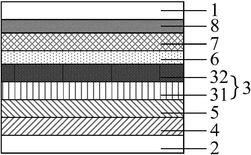
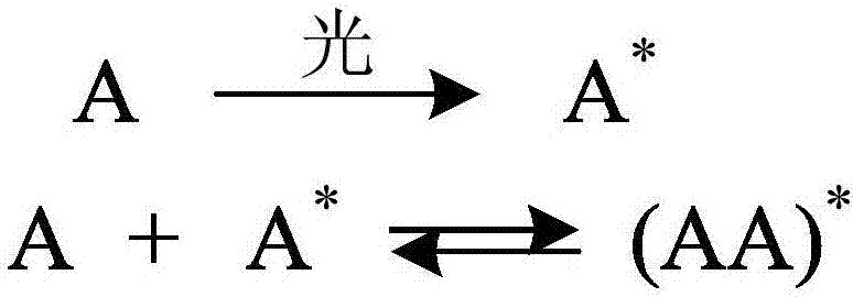
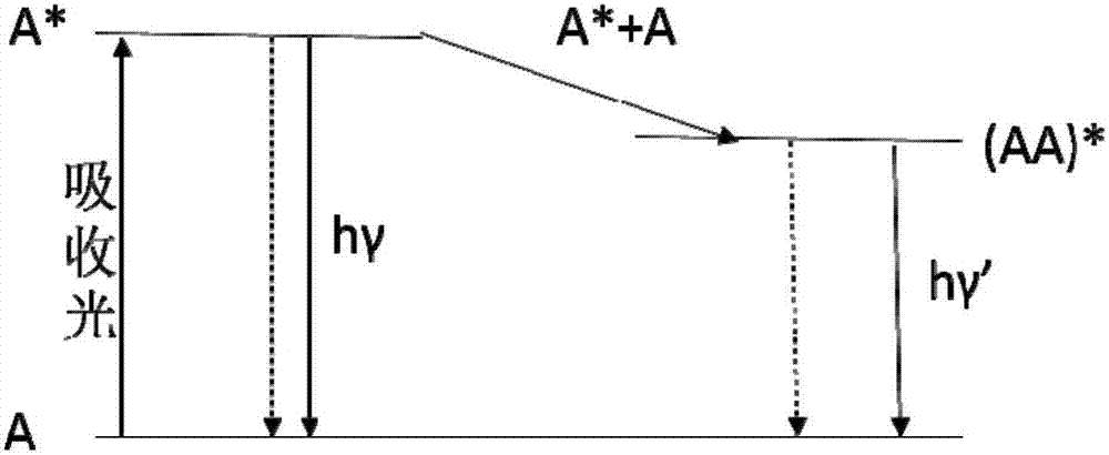
[0033] Please refer to Figure 1 to Figure 5 , the present embodiment provides an organic electroluminescent device, comprising a cathode 1, an anode 2, and a functional layer 3 between the cathode 1 and the anode 2; Layer 31 and the second light-emitting layer 32, the first light-emitting layer 31 includes the first blue light-emitting material, the first light-emitting layer 31 and the second light-emitting layer 32 form a composite product after the cathode 1 and the anode 2 are energized, to emit a color different from blue light of light.

[0034] The first luminescent layer 31 includes the first blue luminescent material, the cathode 1 and the anode 2 form an electric field after being energized, and the first blue luminescent material and the materials in the second luminescent layer 32 form different composite products under the action of the electric field, The composite product can emit red light or green light. Therefore, in this embodiment, the same material can b...

Embodiment 2

[0074] This embodiment provides an OLED substrate, including the organic electroluminescent device of Embodiment 1.

[0075] Among them, the organic electroluminescent device includes a red organic electroluminescent device and a green organic electroluminescent device, and the OLED substrate also includes a blue organic electroluminescent device; the first light-emitting layer and the second light-emitting layer of the red organic electroluminescent device The light emitting layer, the first light emitting layer of the green organic electroluminescent device, and the light emitting layer of the blue organic electroluminescent device are made of the same blue light emitting material.

[0076] In this embodiment, the structure of the blue organic electroluminescent device can be as follows Figure 6 As shown, specifically, a hole injection layer 4 , a hole transport layer 5 , a first light emitting layer 31 , a hole blocking layer 6 , an electron transport layer 7 , an electron...

Embodiment 3

[0080] This embodiment provides a display device, including the OLED substrate of Embodiment 2. The display device can be: electronic paper, OLED panel, mobile phone, tablet computer, TV, monitor, notebook computer, digital photo frame, navigator and any other product or component with display function.

[0081] The display device of this embodiment includes the OLED substrate of Embodiment 2, wherein the same material is used for the hole injection layer and the hole transport layer in the organic electroluminescent devices of different colors, which is very important for the consistency of the inkjet printing experiment. Great improvement, and avoid complex computer programming problems between different light-emitting layer materials.


PUM


Abstract

The invention provides an organic electroluminescent device, an OLED substrate, and a display device, and belongs to the display technology field. The problems of the conventional organic electroluminescent devices such as low ink-jet printing experiment continuity during the preparation process thereof and requirements on complicated computer programs between different luminescent layers are solved. The organic electroluminescent device comprises a cathode, an anode, and a function layer disposed between the cathode and the anode. The function layer comprises a first luminescent layer and a second luminescent layer, which are sequentially arranged in a direction away from the anode. The first luminescent layer comprises a first blue light luminescent material, and after the cathode and the anode are electrified, the first luminescent layer and the second luminescent layer are used to form a composite product to emit light, the color of which is different from the color of the blue light.

Description

technical field [0001] The invention belongs to the field of display technology, and in particular relates to an organic electroluminescent device, an OLED substrate and a display device. Background technique [0002] OLED (Organic Light Emitting Diode, Organic Light Emitting Diode) display device has self-illumination, no backlight module, high contrast and definition, wide viewing angle, full curing, suitable for flexible panels, good temperature characteristics, low power consumption, A series of excellent characteristics such as fast response speed and low manufacturing cost have gradually become one of the key development directions of a new generation of flat panel display devices. With the rapid development of OLEDs, lighting and display products have been launched one after another. [0003] Inkjet printing polymer electroluminescent display technology has the advantages of low cost, simple process, and easy realization of large size. With the continuous research and...

Claims


Application Information

Patent Timeline
IPC IPC(8): H01L51/50H01L27/32
CPCH10K71/135H10K50/13H10K50/11H10K59/10H10K50/00H10K50/14H10K50/15H10K50/16H10K50/17H10K50/18H10K50/19H10K50/81H10K50/82H10K50/125H10K50/171H10K59/00H10K59/30H10K59/32H10K85/633H10K2101/10
Inventor 胡月许名宏廖金龙宋丽芳范招康
Owner BOE TECH GRP CO LTD
Learn More