Photoacoustic and ultrasonic simultaneous imaging system and method for imaging superficial parts

A synchronous imaging and ultrasound technology, applied in the fields of ultrasound/sonic/infrasonic Permian technology, ultrasonic/sonic/infrasonic image/data processing, ultrasonic/sonic/infrasonic diagnosis, etc. Poor specificity, weak specificity and other problems, to achieve the effect of high scanning speed, large imaging depth and high resolution

Active Publication Date: 2018-09-18
广州美神生物科技有限公司
View PDF1 Cites 1 Cited by
  • Summary
  • Abstract
  • Description
  • Claims
  • Application Information

AI Technical Summary

Problems solved by technology

[0003] 1) X-ray breast CT / analog or digital mammary machine, imaging uses radioactive X-rays, which is potentially harmful to health, and is not suitable for repeated detection in a short period of time; breast position and Technicians have high requirements for operation, and it is easy to form blind spots in imaging; the analog or digital mammography machine also needs to compress the breast, and the compression force is usually above 50N, which makes the patient experience more painful; for East Asian women with rich soft tissue structure, imaging The contrast is not high and the specificity is not strong;
[0004] 2) Breast infrared light examination and treatment equipment has poor resolution and specificity, which is not conducive to the identification of lesions; it only has two-dimensional imaging capabilities and cannot provide accurate three-dimensional position information;
[0005] 3) Breast nuclear magnetic resonance MRI, like breast CT, has higher requirements for fixed position and operation skills; the cost of examination for patients is higher; it is contraindicated for pregnant women;
[0006] 4) Breast ultrasound detectors have poor imaging resolution and specificity; it is difficult to identify early pathological features such as tiny calcifications
This patent application discloses a B-probe-type photoacoustic imaging breast scanner and its scanning method. Photoacoustic imaging is applied to breast imaging. However, the application of photoacoustic technology combined with a mature ultrasound system needs to overcome some key technical problems, such as The control and acquisition of photoacoustic signals, signal processing, and coupling with ultrasonic signals, etc., have great technical difficulties in actual operation

Method used


Image

  • Photoacoustic and ultrasonic simultaneous imaging system and method for imaging superficial parts
  • Photoacoustic and ultrasonic simultaneous imaging system and method for imaging superficial parts
  • Photoacoustic and ultrasonic simultaneous imaging system and method for imaging superficial parts

Examples


Embodiment 1

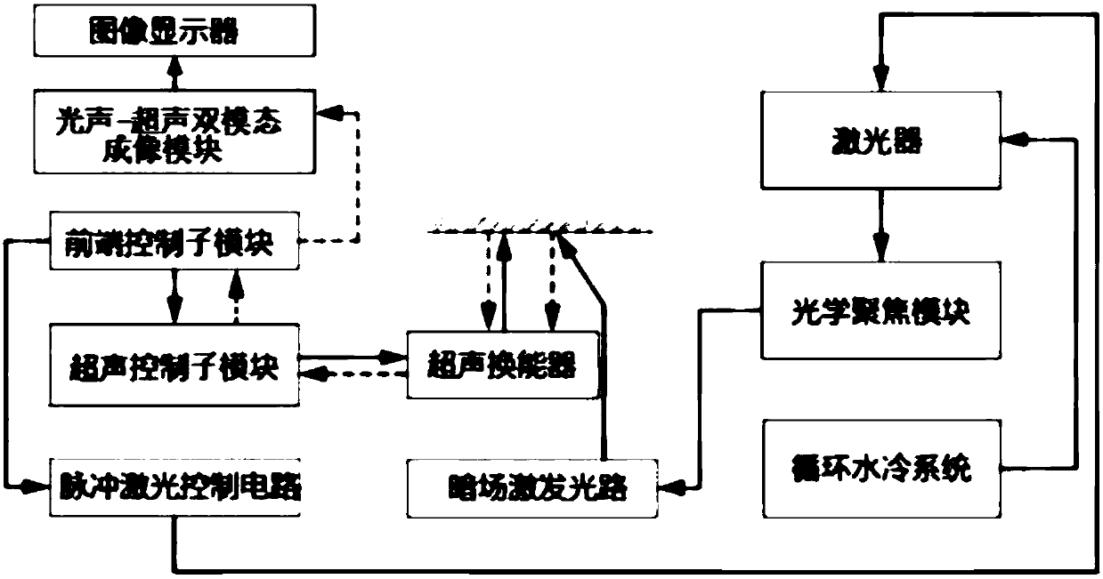
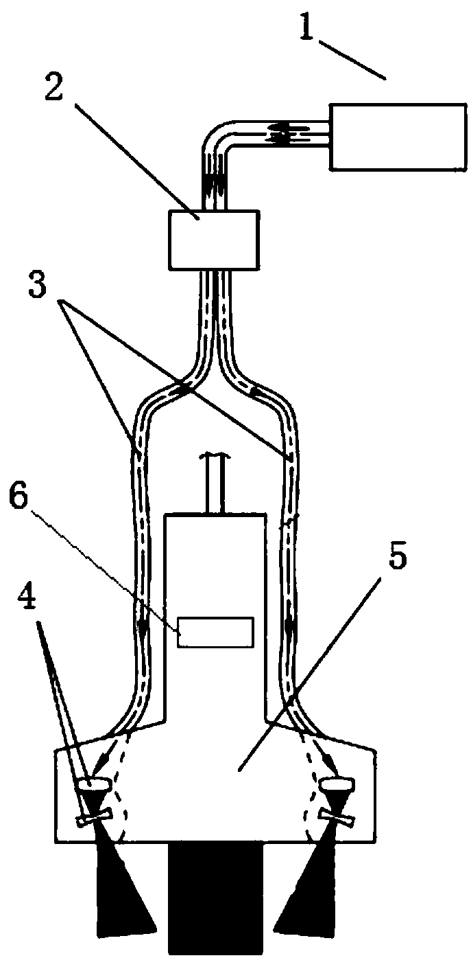
[0039] Such as figure 1 and figure 2 As shown, the photoacoustic and ultrasonic synchronous imaging system for imaging superficial parts includes a connected laser 1 and a photoacoustic-ultrasonic dual-mode imaging system, and the laser 1 is used to output laser signals to generate photoacoustic echo signals; The photoacoustic-ultrasound dual-modal imaging system includes a signal control and processing module, a photoacoustic-ultrasonic dual-modal imaging module, an image display and a hand-held photoacoustic probe 5, and the signal control and processing module includes a front-end control sub-module, and an ultrasonic control module. The sub-module, the ultrasonic control sub-module includes an analog voltage modulation circuit, a signal acquisition circuit, an isolation circuit, a preamplification and filtering circuit, a probe selection board and a channel board, which are used to output the ultrasonic signal generated by the ultrasonic transducer To generate ultrasonic...

Embodiment 2

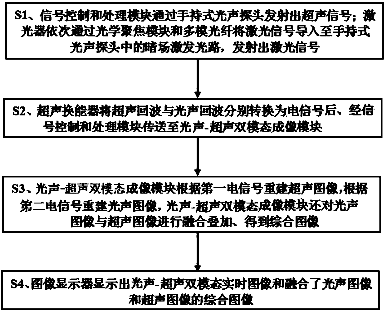
[0044] Such as figure 2 and image 3 As shown, the photoacoustic and ultrasonic simultaneous imaging method for imaging superficial parts includes the following steps:

[0045] S1. The receiving front-end control sub-module controls the laser 1 and the ultrasonic control sub-module to output the laser signal and the ultrasonic signal synchronously. The ultrasonic signal and the laser signal respectively reach the superficial part to be detected through the hand-held photoacoustic probe 5, wherein the laser signal is optically focused After the module 2 is coupled into two sets of multi-mode optical fibers 3, the two sets of multi-mode optical fibers 3 lead the laser signals into two sets of dark-field excitation optical paths 4 respectively, and the dark-field excitation optical paths 4 shape the laser signals and project them uniformly according to the set angle and shape To the superficial part to be detected, the dark field excitation light path 4 preferably includes a cy...


PUM


Abstract

The invention discloses a system and a method for opto-acoustic and ultrasonic synchronous imaging used for superficial position imaging, and relates to the technical field of medical examination imaging equipment. The system comprises a laser and an opto-acoustic-ultrasonic dual-mode imaging system. The opto-acoustic-ultrasonic dual-mode imaging system comprises a signal control and processing module, an opto-acoustic-ultrasonic dual-mode imaging module, an image display, and a handheld opto-acoustic probe. The handheld opto-acoustic probe is also internally provided with an ultrasonic transducer. The laser is used to output laser signals. The signal control and processing module is used to output ultrasonic signals. The handheld opto-acoustic probe is used to transmit laser signals and ultrasonic signals to a to-be-detected superficial position. The opto-acoustic-ultrasonic dual-mode imaging module is used to rebuild an ultrasonic image and an opto-acoustic image, and send the images to the image display to display. The system is high in sensitivity and large in imaging depth, and can be flexibly applied in human body superficial position imaging of breasts, sentinel node, thyroid, prostate, etc.

Description

technical field [0001] The invention relates to the technical field of medical examination imaging equipment, in particular to a photoacoustic and ultrasonic synchronous imaging system and method for imaging superficial parts. Background technique [0002] After years of continuous innovation in medical engineering technology, tumor imaging detection instruments based on imaging methods have been widely used, providing an important basis for medical detection, diagnosis and treatment. Breast cancer is a highly harmful tumor disease. The main imaging equipment used in breast tumor detection in the prior art has different technical characteristics, but there are still certain problems: [0003] 1) X-ray breast CT / analog or digital mammary machine, imaging uses radioactive X-rays, which is potentially harmful to health, and is not suitable for repeated detection in a short period of time; breast position and Technicians require a high level of operation, which is easy to form ...

Claims


Application Information

Patent Timeline
Patent Type & Authority Patents(China)
IPC IPC(8): A61B5/00A61B8/08A61B8/00
CPCA61B5/0035A61B5/004A61B5/0095A61B8/0825A61B8/085A61B8/4444A61B8/5261
Inventor 庞志强陈健桦丁汝波
Owner 广州美神生物科技有限公司
Why Eureka
Try Eureka