
Production process of high-efficient multi-grid welding strip

A production process and welding strip technology, which is applied to the production process field of multi-grid high-efficiency welding strips, can solve the problems of burning module cells, reducing the photoelectric conversion efficiency of modules, affecting the normal use of module cells, etc., so as to increase the welding contact area, Improve the effect of local overheating

Inactive Publication Date: 2017-09-15
苏州赛历新材料科技有限公司
View PDF6 Cites 4 Cited by
  • Summary
  • Abstract
  • Description
  • Claims
  • Application Information

AI Technical Summary

Problems solved by technology

With the development of multi-busbar technology, due to the large number of ribbons, the width of the ribbons is relatively high. The use of conventional ribbons has the following disadvantages: the ribbon width is large, and the shielding area is large when applied to components, resulting in The photoelectric conversion efficiency decreases and the current loss increases
[0003] In order to meet the development requirements of multi-busbar cells, the thin grid ribbons developed at this stage are mostly round wire ribbons. The advantages of this ribbon are: 1. Increase the output power by about 5%; 2. Save the cost of silver paste 20%; Disadvantages of this ribbon: 1. The contact area is small when soldered to the module cells, resulting in excessive resistance of the contact points; 2. During use, it is easy to cause local overheating of the module cells, and even cause the module cells to burn out. Affect the normal use of module cells

Method used


Image

  • Production process of high-efficient multi-grid welding strip
  • Production process of high-efficient multi-grid welding strip

Examples


Embodiment 1

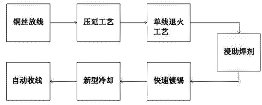
[0027] Such as figure 1 as shown,

[0028] Single line process:

[0029] Copper wire pay-off: the oxygen-free copper wire is unwound by a shaftless constant tension pay-off mechanism;

[0030] Calendering process: the hard copper wire is pressed into a hard flat wire by a calendering wheel (use software simulation technology to set the parameters initially, and then conduct repeated tests to determine the best parameters required for the product, and set the finishing rolling parameters according to product performance requirements);

[0031] Single-wire annealing process: pass the hard flat wire through the annealing chamber to make it into a soft flat wire [Using the principle of resistance heating (annealing temperature is 350°C-650°C), the hard flat wire becomes the required soft flat wire wire; the process must be guaranteed in an oxygen-free state, so a protective gas must be used to protect the annealed copper wire to avoid oxidation caused by contact with air];

[0...

Embodiment 2

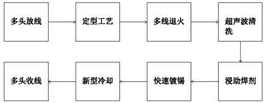
[0037] Such as figure 2 as shown,

[0038] Multi-line process:

[0039] Multi-head pay-off: use multi-axis oxygen-free copper wire to pay off with multi-head pay-off equipment (the pay-off mechanism has a guide shaft);

[0040] Shaping process: multiple groups of oxygen-free copper wires are turned into the required hard flat wires through eye mask equipment (this process turns hard round wires into hard flat wires);

[0041] Multi-wire annealing: multiple groups of hard flat wires undergo a tubular annealing process to turn hard flat wires into soft flat wires (this process changes hard flat wires into soft flat wires);

[0042] Ultrasonic cleaning: Ultrasonic cleaning of the soft flat wire with clean water;

[0043] Soldering flux: use the guide system to soak the soft flat wires that have been cleaned in multiple groups through the flux (there are two kinds of flux, one is a mixture of active agent and organic alcohol, this flux volatilizes quickly, without Residue, bu...


PUM


Abstract

The invention discloses a production process of a high-efficient multi-grid welding strip. The process comprises the following steps: 1) paying off copper wires; 2) carrying out calender setting; 3) annealing; 4) soaking in soldering flux; 5) quickly tin-plating; 6) cooling; 7) taking up the wires. According to the production process, under a condition of guaranteeing the specification of a round wire welding strip, the round wire is made into an ellipse wire, so that the welding contact area of the round wire and an assembly battery cell is increased; moreover, under a condition of guaranteeing the welding performance of the round wire, the local overheat phenomenon of the assembly battery cell is improved.

Description

technical field [0001] The invention belongs to solar photovoltaic products, and in particular relates to a production process of multi-grid high-efficiency soldering strips. Background technique [0002] Photovoltaic soldering strips, also known as tinned copper strips or tinned copper strips, are divided into bus strips and interconnection strips, and are used for the connection of photovoltaic module cells. The width of the ribbon depends on the busbar width of the cell, and the thickness depends on the thickness of the cell and the amount of short-circuit current. With the development of multi-busbar technology, due to the large number of ribbons, the width of the ribbons is relatively high. The use of conventional ribbons has the following disadvantages: the ribbon width is large, and the shielding area is large when applied to components, resulting in The photoelectric conversion efficiency decreases and the current loss increases. [0003] In order to meet the devel...

Claims


Application Information

Patent Timeline
Patent Type & Authority Applications(China)
IPC IPC(8): B23K35/40C23C2/08C23C2/40B21C37/04
CPCB23K35/40B21C37/042C23C2/08C23C2/40
Inventor 李经泽胡云宗
Owner 苏州赛历新材料科技有限公司
Learn More