A prefabricated concrete column foot node with outsourcing steel plate and its construction method

A technology of reinforced concrete columns and outer steel plates, applied in the directions of columns, piers, pillars, etc., can solve the problems of high post-earthquake repair cost, difficulty in accurately fixing grouting sleeves, and insufficient restraint of root stirrups, so as to eliminate the need for fixing tooling. , the effect of increased thickness and simple structure

Active Publication Date: 2019-04-23
CHINA STATE CONSTRUCTION ENGINEERING CORPORATION
View PDF5 Cites 0 Cited by
  • Summary
  • Abstract
  • Description
  • Claims
  • Application Information

AI Technical Summary

Problems solved by technology

[0004] The purpose of the present invention is to provide a prefabricated concrete column foot joint with outsourcing steel plates and its construction method, to solve the problems of insufficient root stirrup restraint, high post-earthquake repair cost, and grouting sleeve production in the existing prefabricated concrete column foot joint. Difficult to precisely fix technical issues in

Method used


Image

  • A prefabricated concrete column foot node with outsourcing steel plate and its construction method
  • A prefabricated concrete column foot node with outsourcing steel plate and its construction method
  • A prefabricated concrete column foot node with outsourcing steel plate and its construction method

Examples


Embodiment 1

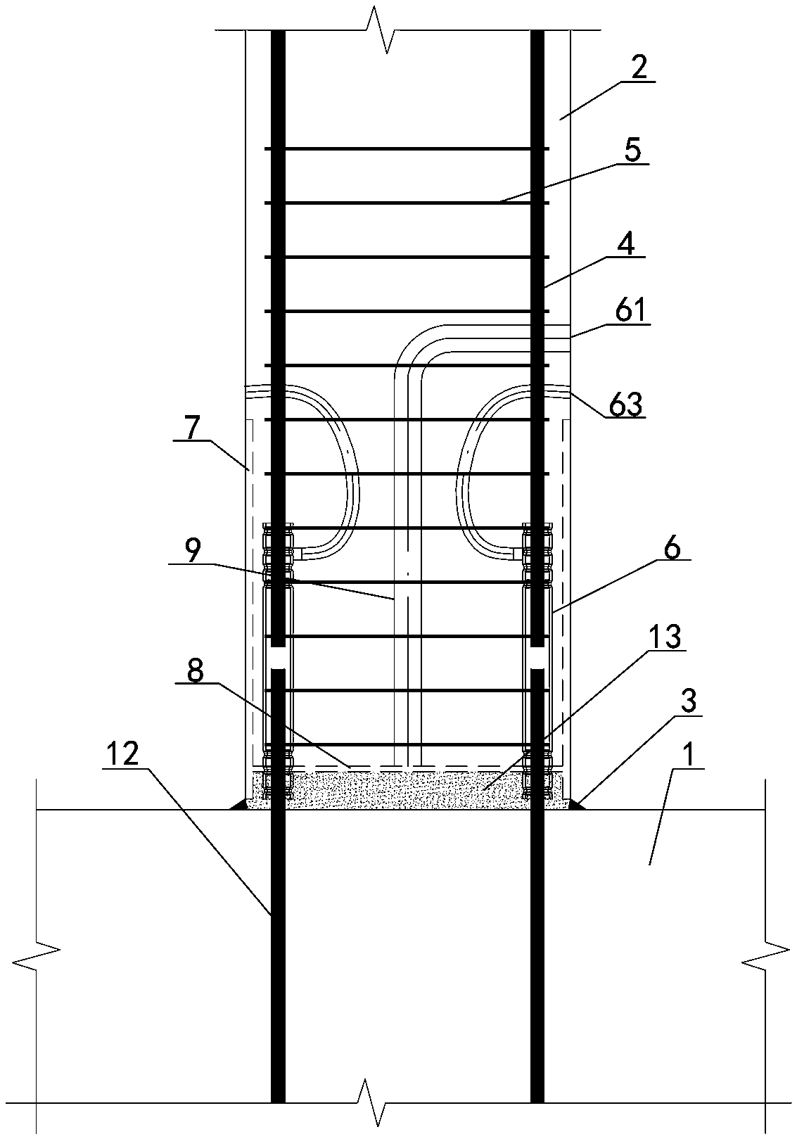
[0042] Embodiment one sees Figure 1-3 As shown, a prefabricated concrete column base node covered with steel plates includes an upper prefabricated reinforced concrete column 2 and a lower reinforced concrete foundation 1 that are spliced ​​vertically. The prefabricated reinforced concrete column 2 is embedded with a Column inner longitudinal bars 4, column inner stirrups 5, and grouting sleeve devices 6 that are evenly distributed around a circle, the reinforced concrete foundation 1 is pre-embedded with foundation anchorage insertion reinforcement bars 12, and the foundation anchorage insertion reinforcement bars 12 and column inner longitudinal reinforcement 4 is connected through the grouting material 13 filled in the grouting sleeve device 6, and the joint between the reinforced concrete foundation 1 and the prefabricated reinforced concrete column 2 is also filled with the grouting material 13.

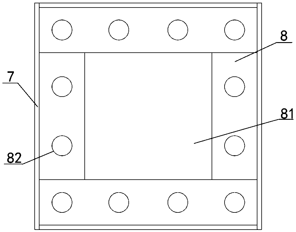
[0043] The node also includes an outsourcing steel plate cylinder 7 that i...

Embodiment 2

[0051] Embodiment two see Figure 4-5 As shown, the difference from Embodiment 1 is that the grouting sleeve device 6 is a second sleeve with independent grouting holes 62 and independent grouting holes 63, and the grouting material 13 in the second sleeve and the joint cavity is For split casting, the independent grouting hole 62 and the independent grouting hole 63 communicate with the sleeve through corresponding grouting pipes embedded in the column.

Embodiment 3

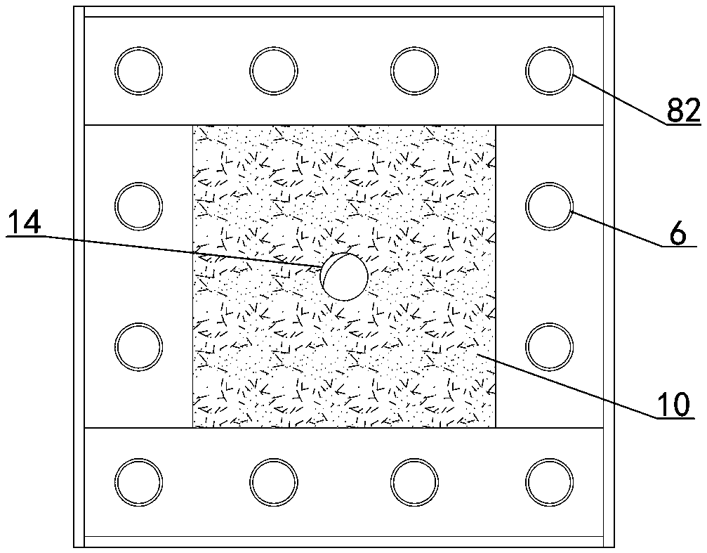
[0052] Embodiment three see Figure 6-7 As shown, the difference from Embodiment 1 is that the grout circulation pipe 9 in the column is a pipe prefabricated integrally with the column, and the bottom of the prefabricated reinforced concrete column 2 shown is integrally prefabricated with a shear key body 11, and the shear key body The surrounding edge of 11 wraps the grouting sleeve device 6 and is flush with the bottom end of the outer steel plate cylinder 7. The middle part of the shear key body 11 is concave in a bucket shape, and the concave bucket shape forms a cavity with the top surface of the foundation. The grouting material 13 is filled, and the middle part of the shear key body 11 is reserved with a grouting hole 14 for the grout circulation pipe in the column.


PUM


Abstract

An assembled concrete column foot node with outsourcing steel plate and its construction method, the column foot node includes a prefabricated reinforced concrete column, a reinforced concrete foundation, an outsourcing steel plate cylinder that is integrally prefabricated with the concrete column and externally enclosed at the column foot, and the outsourcing steel plate There is a gap between the bottom of the cylinder and the upper surface of the foundation, and the outer side of the gap is filled with sealing materials. The joint also includes an annular rib that is seamlessly connected horizontally with the inner wall of the outer cladding steel tube, and has a rib hole in the middle. The annular rib plate has a sleeve hole suitable for the grouting sleeve device, and the edge of the steel plate tube, the annular rib plate, the sealing material and the upper surface of the foundation form a closed joint cavity, and the joint cavity is filled with the grouting material. The invention improves the constraint effect on the concrete at the base of the column, improves the ductility level of the joint at the base of the column, saves the fixing tooling of the sleeve in the component production process, improves the positioning accuracy of the sleeve of the prefabricated column, and has a simple structure and convenient construction.

Description

technical field [0001] The invention belongs to the field of prefabricated concrete structure buildings, in particular to a column base node of a prefabricated concrete outsourcing steel plate and a construction method thereof. Background technique [0002] Under the action of rare earthquakes, the joints of the column feet of the concrete frame structure are easy to yield and form plastic hinges. Especially when the rotation angle is large, the concrete at the root often peels off or is crushed due to insufficient restraint by the column stirrups. The failure form of the column foot joints not only increases the difficulty of post-earthquake repairs, but also greatly increases the economic cost of repairs. [0003] Although the commonly used socket grouting joints in prefabricated concrete buildings have the same mechanical performance as cast-in-place structures, they also have the problem that it is not easy to repair after an earthquake; at the same time, in the process ...

Claims


Application Information

Patent Timeline
Patent Type & Authority Patents(China)
IPC IPC(8): E02D27/42E04C3/34E04B1/98E04H9/02E04G21/00
CPCE02D27/42E04C3/34E04G21/00E04H9/021E04H9/025E04G23/0218E04B1/21
Inventor 郭海山李黎明齐虎范昕王冬雁耿娇田力达刘康李明李桐谢永兰
Owner CHINA STATE CONSTRUCTION ENGINEERING CORPORATION
Why Eureka
Try Eureka