Spiral-flow type defoaming device

A defoaming device and swirling technology, which are applied in the field of defoaming of water bodies, can solve the problems of corroding metal structures, vegetation, foam overflow, polluting the factory area, etc. Effect

Pending Publication Date: 2017-09-19
CHINA INST OF WATER RESOURCES & HYDROPOWER RES
View PDF5 Cites 2 Cited by
  • Summary
  • Abstract
  • Description
  • Claims
  • Application Information

AI Technical Summary

Problems solved by technology

After these large amounts of light yellow foam are discharged into the environmental sea area with the cooling water, they are scattered around under the action of ocean currents, etc., which not only seriously affects the water quality and appearance of the receiving water area, but also the splashed salty mist will seriously corrode the metal near the drain. Vegetation on structures and surfaces
In some special cases, the foam may overflow into the plant area, seriously affecting the environment around the power plant
[0003] The existing coastal power plants have adopted certain energy dissipation and defoaming measures, but it is difficult to adapt to the needs of tide level changes. Under the condition of low tide level, the drainage water is easy to be aerated and carried to the open sea, forming a foam pollution zone; the second is that the existing projects The measures cannot completely prevent the generation of foam. Basically, measures such as foam blocking walls are used to contain the foam in the area behind the siphon well weir. The area behind the weir gradually accumulates foam, which is prone to foam overflowing the siphon well and polluting the factory area. Further engineering measures are needed to suppress it foam accumulation
In short, the existing engineering measures cannot fully meet the needs of drainage and anti-foaming in sea area projects. To explore more suitable drainage anti-foaming and anti-foaming methods for coastal power plants will help eliminate or reduce the impact of foam on the environment and improve the surrounding waters of power plants. environmental significance

Method used


Image

  • Spiral-flow type defoaming device

Examples


Embodiment Construction

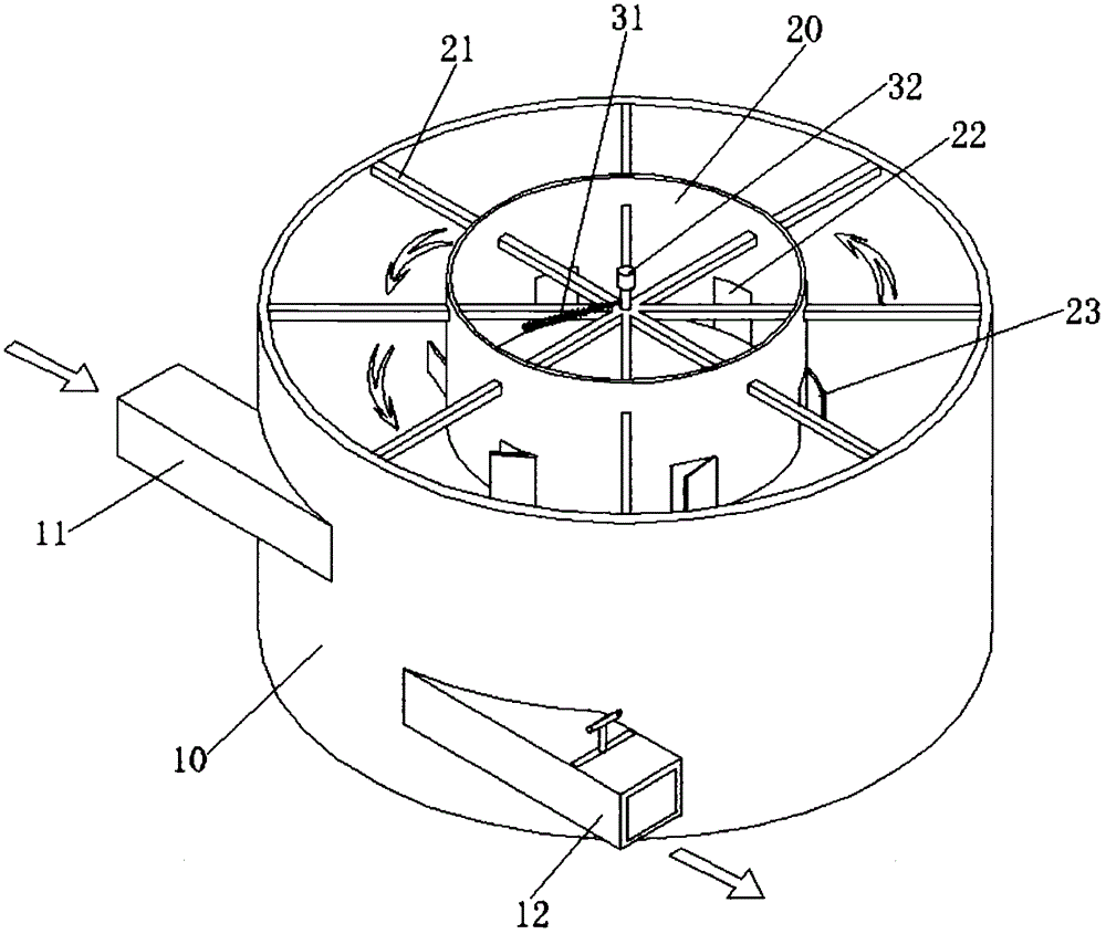
[0017] Such as figure 1 As shown, the swirl defoaming device is mainly composed of a swirl defoamer 10, a foam collector 20 and a brush defoamer, the swirl defoamer 10 is a drum structure, the swirl defoamer The flow defoaming body is provided with a tangential direction diversion into the inflow port 10 in the swirl diversion defoaming body, and the inflow port 10 of the tangential direction diversion and the barrel wall of the swirl diversion defoamer make the incoming foamy water generate a swirl Flow force, the centrifugal force generated by the swirl makes the foam gather towards the center of the swirl defoamer. The outer wall of the swirl diversion defoaming body is also provided with a water outlet 12, the water outlet 12 is arranged along the tangential direction of the swirl diversion defoamer outer wall, and the horizontal position of the water outlet 12 is lower than that of the flow. The inlet 11 and the water outlet 12 allow the water after centrifugation to sep...


PUM


Abstract

A spiral-flow type defoaming device is characterized by comprising a spiral-flow guide defoaming body. A flow inlet for tangentially guiding flow into the spiral-flow guide defoaming body is arranged outside the spiral-flow guide defoaming body, a foam collector is arranged in the spiral-flow guide defoaming body, and a power-driven brush defoamer is assembled on the foam collector. The spiral-flow type defoaming device is reasonable in structural design and obvious in defoaming effect and drives foam to be collected in the foam collector by spiral-flow centrifugal force for guiding water with foam in the spiral-flow guide defoaming body, and mechanically driven brush defoaming agents can perform low-cost efficient defoaming operation. The spiral-flow type defoaming device is simple in structure and low in operating cost and can be widely applied to defoaming operation for refrigerating cycle by surface water in a power plant.

Description

technical field [0001] The invention belongs to the defoaming technology of water bodies, and in particular relates to a swirl type defoaming device for mechanical cooling of water bodies in power plants. Background technique [0002] Thermal power or nuclear power plants generally adopt a once-through water supply system that uses surface water such as seawater as a cooling water source, which will inevitably lead to a large amount of circulating cooling water being redischarged into the environmental water body. In order to reduce operating costs and ensure the safe operation of the water intake and drainage system, under normal circumstances, power plant drainage adopts a siphon well outflow method, that is, a siphon well is provided at the front edge of the drainage outlet, and a certain elevation weir is installed inside the siphon well to reduce the tide level in the open sea. The impact of the change on the upstream section of the siphon well. In view of the constant...

Claims


Application Information

Patent Timeline
IPC IPC(8): C02F1/20C02F1/38C02F103/02
CPCC02F1/20C02F1/38C02F2103/023C02F2201/002
Inventor 谭水位秦晓曾利贺益英杨帆
Owner CHINA INST OF WATER RESOURCES & HYDROPOWER RES
Why Eureka
Try Eureka