Copper-plastic compound pressure reduction-type backflow preventer and manufacturing method thereof
A backflow preventer, copper-plastic composite technology, applied in the direction of control valves, functional valve types, valve details, etc., can solve the problems of insufficient mechanical performance and structure of core load-bearing parts, heavy weight, difficult transportation, poor bonding force, etc.
- Summary
- Abstract
- Description
- Claims
- Application Information
AI Technical Summary
Problems solved by technology
Method used
Image
Examples
Embodiment 1
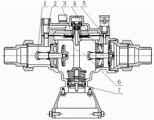
[0029] A copper-plastic composite decompression type backflow preventer, which is provided with a main body for the first check valve 1 and a second check valve, which are obtained through square-turn-circle hot extrusion and swaging to obtain a conical forging streamline that is concentrated toward the inner hole. 4, the forging of the supporting column, the working part 3 which is arranged between the first check valve 1 and the second check valve 4 and inserted into the working chamber 6, and the first liquid passage connecting the working part 3 and the first check valve 1 2 and the second liquid channel 5 connecting the working part 3 and the second check valve 4; the bottom of the working part 3 is also connected with a pressure stabilizing device 7; the shell of the backflow preventer is a composite structure with polyamide outside and tin bronze inside.
[0030] The method for manufacturing above-mentioned forged parts, comprises the following steps:
[0031] 1) Pre-pr...
Embodiment 2
[0050] The whole is consistent with Example 1, the difference is:
[0051] The method for manufacturing above-mentioned forged parts, comprises the following steps:
[0052] 2) forging
[0053] ①Heat the tin bronze billet through a vacuum resistance furnace to a temperature 30°C higher than its theoretical solid solution temperature, keep it warm for 1.5min / mm based on the diameter of the copper billet, and then take it out of the furnace, and fix the bottom of the copper billet on the rotary push device ;
[0054] ②The forging hammer head linked with the rotary push device is pushed by the hydraulic generating device, and the copper billet is extruded into a forging billet with a nearly square cross-section at a feed rate of about 5% for each deformation and a final deformation ratio of 45% to deform the copper billet. The length of one forging deformation of the blank is one forging cycle. After the last forging in one cycle is completed, the forging hammer head is fixed o...
Embodiment 3
[0062] The whole is consistent with Example 1, the difference is:
[0063] The method for manufacturing above-mentioned forged parts, comprises the following steps:
[0064] 2) forging
[0065] ① Heat the tin bronze billet through a vacuum resistance furnace to a temperature 50°C higher than its theoretical solid solution temperature, keep it warm for 1.8min / mm based on the diameter of the copper billet, and then take it out of the furnace, and fix the bottom of the copper billet on the rotary push device ;
[0066] ②The forging hammer head linked with the rotary push device is pushed by the hydraulic generating device, and the copper billet is extruded into a forging billet with a nearly square cross-section at a feed rate of about 5% for each deformation and a final deformation ratio of 55% to deform the copper billet. The length of one forging deformation of the blank is one forging cycle. After the last forging in one cycle is completed, the forging hammer head is fixed ...
PUM
 Abstract
Description
Claims
Application Information
 - R&D
- Intellectual Property
- Life Sciences
- Materials
- Tech Scout
- Unparalleled Data Quality
- Higher Quality Content
- 60% Fewer Hallucinations
Browse by: Latest US Patents, China's latest patents, Technical Efficacy Thesaurus, Application Domain, Technology Topic, Popular Technical Reports.
© 2025 PatSnap. All rights reserved.Legal|Privacy policy|Modern Slavery Act Transparency Statement|Sitemap|About US| Contact US: help@patsnap.com

