An uncooled infrared catadioptric panoramic lens
A catadioptric panoramic and uncooled infrared technology, applied in the field of infrared optics, can solve the problems of large amount of original image data, geometric distortion, and low time resolution, and achieve the effect of simple structure, simple structure, and small field of view
- Summary
- Abstract
- Description
- Claims
- Application Information
AI Technical Summary
Problems solved by technology
Method used
Image


Examples
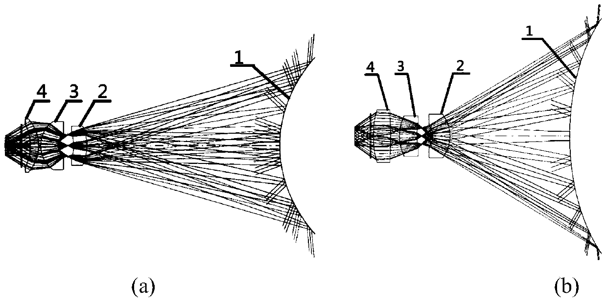
Embodiment 1
[0038] For an uncooled infrared vanadium oxide focal plane detector with a pixel size of 640×512, a pixel center distance of 17 μm, and a working band of 8 μm to 12 μm, a catadioptric infrared panorama with F# of 1, an equivalent focal length of 3 mm, and a working band of 8 μm to 12 μm is designed Lens, the specific performance parameters are:
[0039] (1) Equivalent focal length: 3mm
[0040] (2) F#: 1
[0041] (3) Infrared imaging band range: 8μm~12μm
[0042] (4) Horizontal field of view: 360°
[0043] (5) Vertical field of view during infrared imaging: -70°~+5°
[0044] (6) Infrared imaging MTF:>40%@20lp / mm
[0045] (7) Optical system average transmittance: 88%
[0046] The surface parameters of the optical element designed in Example 1 are shown in Table 1.
[0047] The optical element surface parameter of table 1 embodiment 1
[0048]
[0049]
[0050] The third-order aberrations of each surface of the optical element designed in Table 1 are shown in Table 2....
Embodiment 2
[0055] For an uncooled infrared vanadium oxide focal plane detector with a pixel size of 640×512, a pixel center distance of 17 μm, a working band of 8 μm to 12 μm, and a peak wavelength of 10 μm, the design F# is 1, the equivalent focal length is 4.2 mm, and the working band is 8 μm to 12 μm The catadioptric infrared panoramic lens, the specific performance parameters are:
[0056] (1) Equivalent focal length: 4.2mm
[0057] (2) F#: 1
[0058] (3) Infrared imaging band range: 8μm~12μm
[0059] (4) Horizontal field of view: 360°
[0060] (5) Vertical field of view during infrared imaging: -70°~+5°
[0061] (6) Infrared imaging MTF:>55%@20lp / mm
[0062] (7) Optical system average transmittance: 88%
[0063] The surface parameters of the optical element designed in Example 2 are shown in Table 3.
[0064] The optical element surface parameter of table 3 embodiment 2
[0065]
[0066]
[0067] The tertiary aberrations of each surface of the optical element designed i...
PUM
 Abstract
Description
Claims
Application Information
 - R&D
- Intellectual Property
- Life Sciences
- Materials
- Tech Scout
- Unparalleled Data Quality
- Higher Quality Content
- 60% Fewer Hallucinations
Browse by: Latest US Patents, China's latest patents, Technical Efficacy Thesaurus, Application Domain, Technology Topic, Popular Technical Reports.
© 2025 PatSnap. All rights reserved.Legal|Privacy policy|Modern Slavery Act Transparency Statement|Sitemap|About US| Contact US: help@patsnap.com