Sound insulation barrier with self-power-generation function

A sound insulation barrier and self-generating technology, applied in the direction of generators/motors, piezoelectric effect/electrostrictive or magnetostrictive motors, electrical components, etc., can solve the problem of increasing investment and operating costs, and failure of sound insulation barriers To reduce the cost of operation and maintenance, eliminate hidden dangers, and reduce the single amplitude

Active Publication Date: 2017-09-22
SUZHOU UNIV
View PDF7 Cites 1 Cited by
  • Summary
  • Abstract
  • Description
  • Claims
  • Application Information

AI Technical Summary

Problems solved by technology

[0004] Disadvantages of the existing technology: 1. At present, the focus of noise reduction in China is to weaken the noise source and build a sound insulation barrier in the propagation path, ignoring the damage caused by the sound insulation barrier itself when it is subjected to cyclic loads The effect of noise reduction is weakened
The ultra-fine glass wool sound-absorbing materials that are widely used in China have low strength and are brittle and easy to break. The brittle fracture and dusting make the original homogeneous structure no longer exist, resulting in loosening and failure of bolts and connectors, and damage to the unit board of the sound insulation barrier. The sound insulation barrier fails to effectively absorb and reduce noise
[0005] 2. The daily maintenance workload is heavy and the efficiency is low
However, the internal damage of the sound insulation barrier is not easy to find, which increases the difficulty of daily maintenance, and will result in untimely maintenance and replacement, which is time-consuming and laborious
[0006] 3. There is a lack of a good early warning mechanism along the existing sound insulation barriers in China
Once the sound insulation barrier along the railway and expressway is damaged, if it

Method used


Image

  • Sound insulation barrier with self-power-generation function
  • Sound insulation barrier with self-power-generation function
  • Sound insulation barrier with self-power-generation function

Examples


Embodiment 2

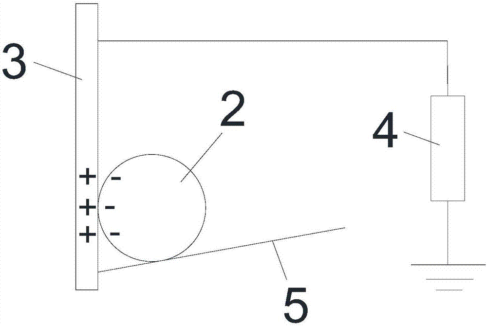
[0042] A sound insulation barrier with self-generating power in this embodiment differs from Embodiment 1 only in that: the contact electrification part 3 includes a second contact electrification part that contacts and separates from the first contact electrification layer to generate charge output. layer (not shown in the drawings), and an electrode capable of inducting charges generated when the first contact electrification layer and the second contact electrification layer are electrically contacted. The electrodes are sensing electrodes, preferably metal electrodes.

[0043] Specifically, the second contact electrification layer is a film attached on the electrode surface, and the film is a polymer material, aluminum foil or copper foil, preferably a polymer material. The polymer material is preferably polytetrafluoroethylene (PTFE), fluorinated ethylene propylene copolymer (FEP) or polyimide (Kapton). The first contact electrification layer can be made of polymer mater...


PUM


Abstract

The invention discloses a sound insulation barrier with a self-power-generation function. The sound insulation barrier comprises a sound insulation wall, a contact electrification part, a plurality of transverse partition plates sequentially arranged from top to bottom, and a plurality of side partition plates sequentially arranged from left to right, wherein the contact electrification part, the transverse partition plates and the side partition plates are arranged in the sound insulation wall and connected to form a plurality of sealed space units; a light ball is arranged in each space unit; the contact electrification part is vertically arranged, and an acute angle is formed between each transverse partition plate and the contact electrification part; each light ball is supported by the corresponding transverse partition plate which forms the space unit where the light ball is located, and can separably abut against the contact electrification part which forms the space unit where the light ball is located; each light ball is provided with a first contact electrification layer which makes contact with the contact electrification part for electrification. When the sound insulation wall is vibrated due to wind pressure or sound waves, the first contact electrification layers are separated from and make contact with the contact electrification part to generate electric charge output.

Description

technical field [0001] The invention relates to a sound insulation barrier with self-generating power. Background technique [0002] With the construction of a large number of roads and bridges, the traffic noise pollution of railways and highways is also becoming more and more serious. Setting up sound insulation barriers on both sides of roads (roads, railways) is a method that is often used to reduce traffic noise. Sound insulation screen is a sound insulation facility. In order to block the direct sound between the sound source and the receiver, a facility is inserted between the sound source and the receiver, so that the sound wave propagation has a significant additional attenuation, thereby weakening the The effect of noise in a certain area where the receiver is located. [0003] There are four common types of sound barriers, namely resistive sound barriers, ordinary transparent sound barriers, microporous plate transparent sound barriers and composite sound barrier...

Claims


Application Information

Patent Timeline
IPC IPC(8): E01F8/00H02N2/18
CPCH02N2/186E01F8/0005
Inventor 唐强陈翔宇顾凡葛超何平曾超胡彦波郝晋序徐来
Owner SUZHOU UNIV
Why Eureka
Try Eureka