Miniaturized cavity backed slot antenna

A slot antenna and cavity-backed technology, applied in the field of cavity-backed slot antennas, can solve the problems of reducing the height of the cavity-backed slot antenna, large plane size of the cavity-backed slot antenna, and failing to realize the overall miniaturization of the antenna, etc. Achieving the effect of avoiding the degradation of bandwidth and radiation efficiency, high bandwidth, reduction of plane size and profile height

Active Publication Date: 2017-10-03
SOUTHWEST JIAOTONG UNIV
View PDF1 Cites 6 Cited by
  • Summary
  • Abstract
  • Description
  • Claims
  • Application Information

AI Technical Summary

Problems solved by technology

The main size parameters of the slot antenna disclosed in this article are: slot length: 118mm; back cavity length: 130mm; back cavity width: 84mm; back cavity height: 2mm; antenna profile height: 7.6mm, as can be seen from the above data: Similar to the shallow-cavity slot antenna mentioned above, although the back cavity height (about 0.016 wavelength) and antenna profile height (about 0.06 wavelength) of the obtained slot antenna are greatly reduced, the slot The size (about 1 wavelength), the back cavity length (about 1 wavelength) and the back cavity width (about 0.67 wavelength) are still large, resulting in the planar size of the finally obtained antenna is still large, of which the length is 150 millimeters (about 1.2 wavelengths), and a width of 146 millimeters (about 1.2 wavelengths), therefore, the above-mentioned technical solution does not realize the overall miniaturization of the antenna
[0004] It can be seen that the prior art research has greatly reduced the back cavity height of the cavity-backed slot antenna and made some progress, however, the planar size of the cavity-backed slot antenna is still relatively large
Moreover, the size of the antenna is proportional to the working wavelength of the antenna. In theory, as the working frequency of the antenna decreases, the working wavelength of the antenna will increase accordingly, and the size of the antenna will increase accordingly.
This poses a major challenge for the miniaturization of low-band antennas

Method used


Image

  • Miniaturized cavity backed slot antenna
  • Miniaturized cavity backed slot antenna
  • Miniaturized cavity backed slot antenna

Examples


Embodiment

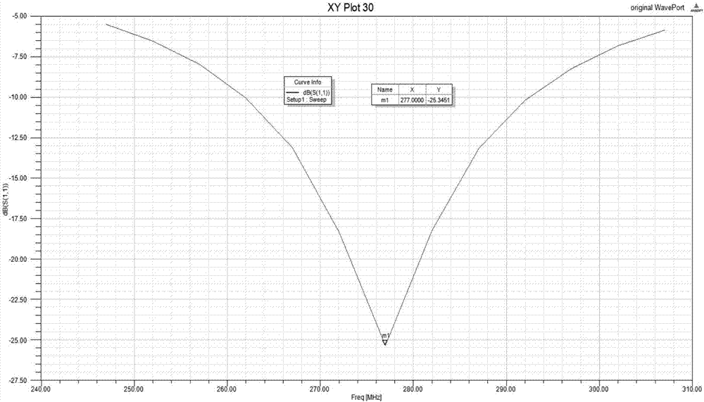
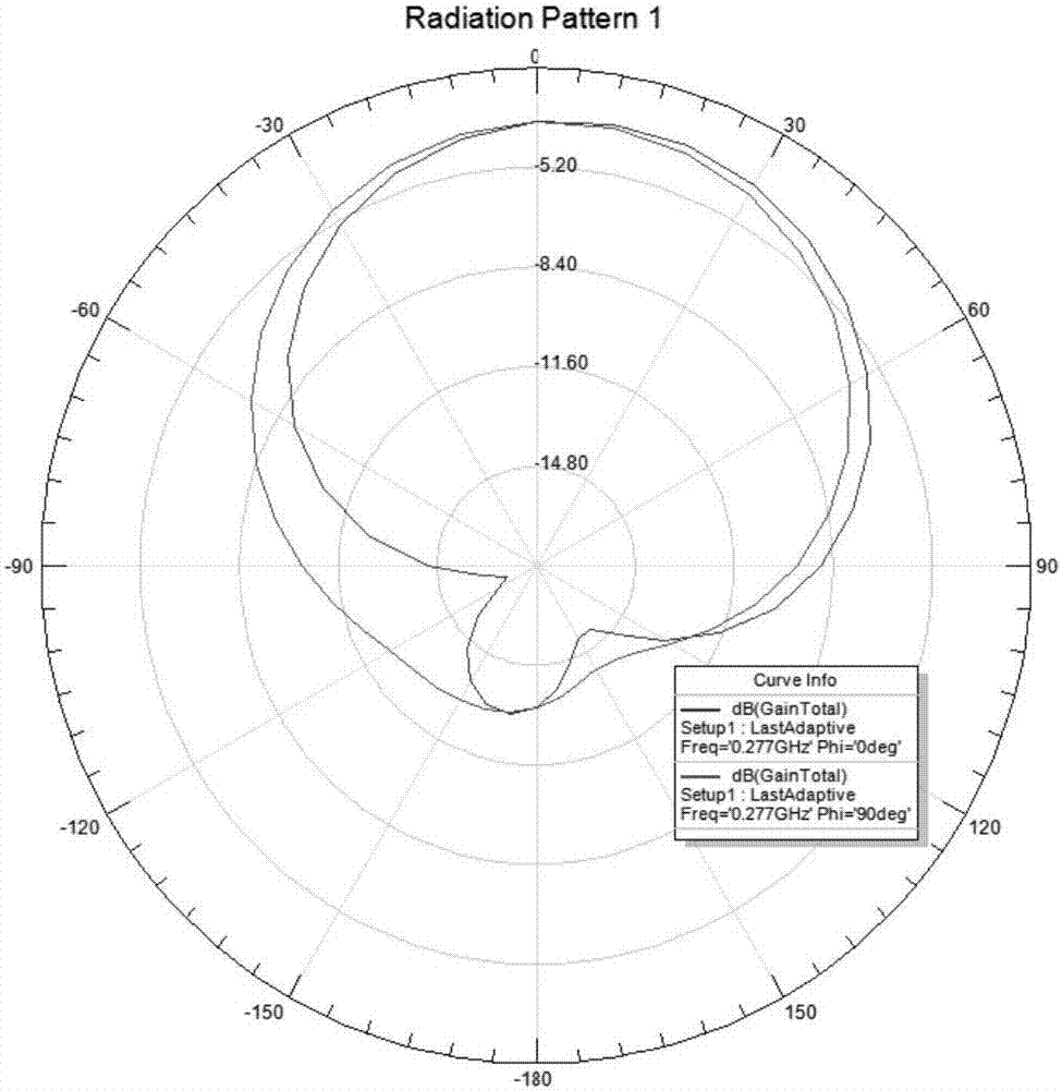
[0040] A specific embodiment of the present invention designs a miniaturized cavity-backed slot RFID antenna, the working frequency range of which is 261-292 MHz, and the center frequency is 277 MHz.

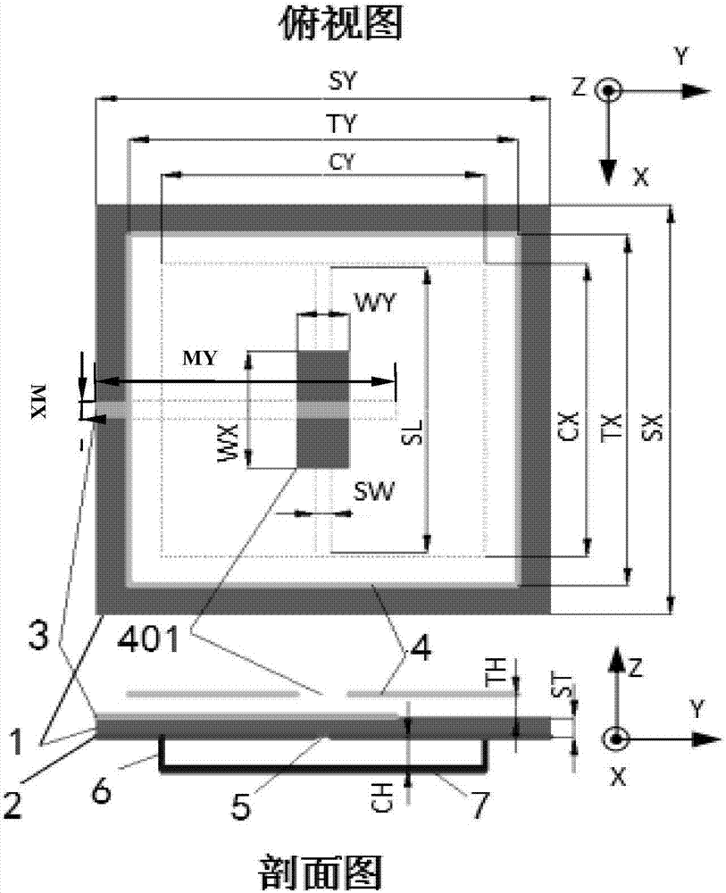
[0041] according to figure 1 The geometric structure, the present embodiment adopts HFSS software to carry out modeling and simulation:

[0042] In this embodiment, the material of the selected ferrite dielectric substrate 1 is an equal magnetic dielectric material, and the relative permittivity ε r =6.86, relative permeability μ r =6.95, the dielectric loss tangent value is 0.0035, and the magnetic permeability loss tangent value is 0.09. According to the calculation and simulation, the size of the ferrite dielectric substrate 1 is: length S X =220mm, width S Y =220mm, thickness S W = 4mm;

[0043] The microstrip feeder 3 is a 50Ω microstrip line, which can be fabricated on a ferrite substrate by using the etching technology of a printed circuit, and its size is: length M ...


PUM


Abstract

The invention provides a miniaturized cavity backed slot antenna and belongs to the technical field of microstrip antennas. In the design of a structure of the miniaturized cavity backed slot antenna, a back cavity with a low profile is adopted, a window metal cover plate suspended above a feed surface is added, a ferrite sheet tightly jointed with a bottom cavity is innovatively designed, and meanwhile, an equal magnetic dielectric ferrite material is taken as a dielectric substrate material; through reasonable application of the technological means, compared with the prior art, the height of the antenna profile is greatly reduced and the plane size of the antenna is also greatly reduced. When the overall miniaturization of the antenna is realized, the sufficient bandwidth is guaranteed and the higher gain is obtained. The designed novel cavity backed slot antenna is of great significance to the antennas working at the low frequency band, such as portable radio frequency identification tag readers, and can be also applied to miniaturization of high frequency or ultrahigh frequency antennas.

Description

technical field [0001] The invention belongs to the technical field of microstrip antennas, in particular to a cavity-backed slot antenna for miniaturization and integration. Background technique [0002] With the rapid development of communication technology, the urgent need for miniaturization of radio frequency equipment has gradually become a key issue in communication systems, and the miniaturization of antennas has therefore become a hot spot in research and application. Conformal microstrip antennas are widely used in wireless communication devices due to their ease of processing and integration, compactness, and low profile. Due to good electrical and mechanical properties, conformal microstrip antennas can effectively conform to reduce wind resistance, so they are very suitable for installation on aircraft, missiles, satellites, ships, vehicles, base stations and other equipment for communication. The cavity-backed slot antenna with microstrip feedback has wider ba...

Claims


Application Information

Patent Timeline
Patent Type & Authority Applications(China)
IPC IPC(8): H01Q13/18H01Q13/10
CPCH01Q13/106H01Q13/18
Inventor 冯全源杜中
Owner SOUTHWEST JIAOTONG UNIV
Why Eureka
Try Eureka