Self-lubricating treatment method for aero-engine bearing

An aero-engine and processing method technology, applied in the field of friction pair self-lubrication, can solve the problems affecting bearing matching accuracy and support stiffness, limiting machining accuracy, bearing channel wear life, etc., to improve the comprehensive performance of friction reduction and wear resistance, The effect of reducing the surface friction coefficient and prolonging the service life

Inactive Publication Date: 2017-10-10
JIANGSU UNIV
View PDF18 Cites 16 Cited by
  • Summary
  • Abstract
  • Description
  • Claims
  • Application Information

AI Technical Summary

Problems solved by technology

The whole layer coating and sintering method is adopted, and the thickness of the lubricating coating reaches 0.5-2.5 mm, which affects the matching accuracy and support rigidity of the bearing
The patent application number 200810235590.0 published in 2009 discloses a three-layer self-lubricating sliding bearing structure. Due to the addition of a porous copper powder sintered layer, the difficulty and cost of the process are greatly improved, and the improvement of machining accuracy is also limited.
[0004] The patent application number 201110148420.0 published in 2011 proposed a laser micro-modeling self-lubricating treatment method for bearings, and the patent application number 201210109126.3 published in 2012 proposed a method for preparing a micro-embedded self-lubricating texture on the surface of gears and cams , the patent application number 201310265852.9 published in 2013 proposed a self-lubricating treatment method for bearings, and the patent application number 201310265925.4 published in 2013 proposed a laser micro-modeling self-lubricating treatment method for friction pairs. The above four The method is to embed solid lubricating materials on the surface of the workpiece after laser micro-modeling treatment, without sputtering DLC-WS 2 Composite coating, affecting anti-friction and wear resistance and lubricating effect
Since the TiN anti-wear coating is only added to the bearing guide surface, the problems of bearing groove wear and short service life cannot be solved
The above-mentioned published patent documents do not relate to the use of laser micro-modeling and sputtering DLC-WS in aero-engine bearings. 2 Self-lubricating method of coating composite treatment

Method used


Image

  • Self-lubricating treatment method for aero-engine bearing
  • Self-lubricating treatment method for aero-engine bearing
  • Self-lubricating treatment method for aero-engine bearing

Examples


Embodiment 1

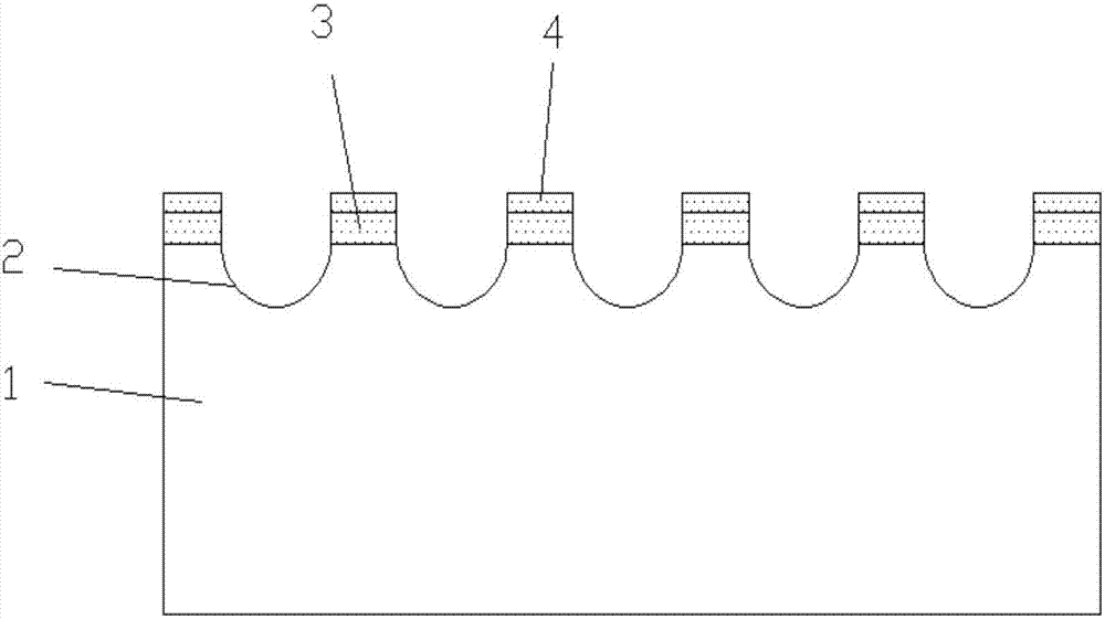
[0026] figure 1 Shown is a schematic diagram of self-lubricating treatment of aero-engine bearings, and the self-lubricating treatment method of aero-engine bearings includes the following steps:

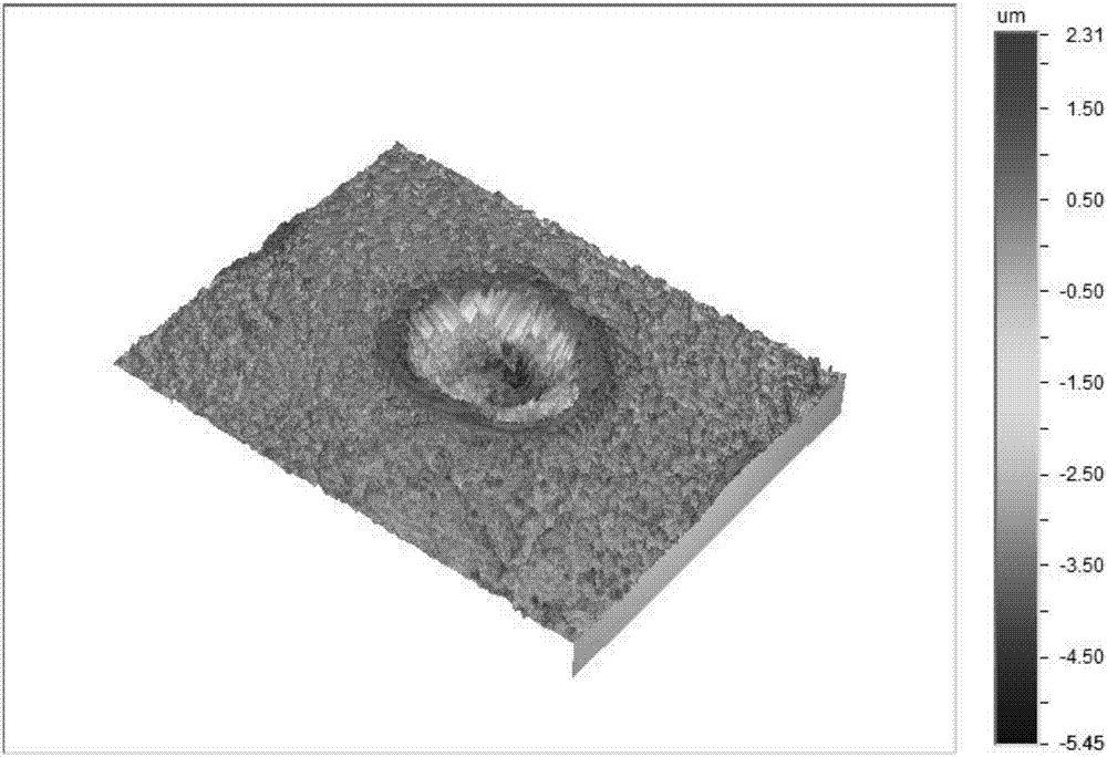
[0027] Step A) For the laser micro-modeling treatment of the aero-engine bearing 1, a diode-pumped Nd:YAG laser processing system is used, the laser wavelength is 532nm, the current intensity is 18.6A, the frequency is 1600Hz, the number of pulses is 4 times, and nitrogen is used as an auxiliary Gas, with a gas pressure of 0.15Mpa, micro-dimples 2 are formed on the rolling or sliding contact parts of the aero-engine bearing 1, and then the surface of the sample is polished with metallographic sandpaper until the slag around the micro-dimples 2 disappears, and the measured surface hardness is still about It is 62-64HRC. Using the WYKO-NT100 three-dimensional measuring instrument for surface micro-geometric topography produced by Veeco, the diameter of a single pit 2 in the sample is...

Embodiment 2

[0033]The self-lubricating treatment method of the aero-engine bearing comprises the following steps:

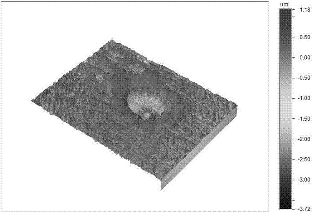
[0034] Step A) For the laser micro-modeling treatment of the aero-engine bearing 1, a diode-pumped Nd:YAG laser processing system is used, the laser wavelength is 532nm, the current intensity is 16.6A, the frequency is 1600Hz, the number of pulses is 3 times, and nitrogen is used as an auxiliary Gas, with a gas pressure of 0.15Mpa, micro-dimples 2 are formed on the rolling or sliding contact parts of the aero-engine bearing 1, and then the surface of the sample is polished with metallographic sandpaper until the slag around the micro-dimples 2 disappears, and the measured surface hardness is still about It is 62-64HRC. Using the WYKO-NT100 three-dimensional measuring instrument for surface microscopic geometric topography produced by Veeco, the diameter of a single pit 2 of the sample is measured to be about 60 μm, the depth is about 4 μm, and the distance between the micro-...

Embodiment 3

[0040] The self-lubricating treatment method of the aero-engine bearing comprises the following steps:

[0041] Step A) For the laser micro-modeling treatment of the aero-engine bearing 1, a diode-pumped Nd:YAG laser processing system is used, the laser wavelength is 532nm, the current intensity is 20A, the frequency is 1600Hz, the number of pulses is 8 times, and nitrogen is used as the auxiliary gas , the gas pressure is 0.15Mpa, micro-dimples are formed on the rolling or sliding contact parts of the aero-engine bearing 1, and then the surface of the sample is polished with metallographic sandpaper until the slag around the micro-dimples 2 disappears, and the measured surface hardness is still about 62 -64HRC. Using the WYKO-NT100 three-dimensional measuring instrument for surface micro-geometric topography produced by Veeco, the diameter of a single pit 2 of the sample is measured to be about 120 μm, the depth is about 10 μm, and the distance between the micro-pit 2 is 220 ...


PUM

PropertyMeasurementUnit
diameteraaaaaaaaaa
depthaaaaaaaaaa
diameteraaaaaaaaaa

Abstract

The invention discloses a self-lubricating treatment method for an aero-engine bearing, and relates to the technical field of aero-engine bearing self-lubricating. The self-lubricating treatment method for the aero-engine bearing comprises the following steps: firstly, performing laser micro-modelling treatment on the surface of the aero-engine bearing, wherein the diameters of micro-pits are 60 to 120 mu m, the depths of the micro-pits are 4 to 10 mu m, the distances of the micro-pits are 150 to 220 mu m, and the area occupation ratio of the micro-pits is 12.5 to 19.6 percent; and secondly, performing magnetron sputtering to form a DLC-WS2 composite coating. By utilizing a composite treatment process and the complementarity and the cooperativity of diversified treatment, comprehensive performance of reducing friction and resisting friction of the aero-engine bearing is improved; wear is reduced; and the service life of the aero-engine bearing under complex working conditions that the rotating speed is 35,000 r / min, the temperature of 300 DEG C and the like is prolonged.

Description

technical field [0001] The present invention relates to friction pair self-lubricating technology, in particular to a self-lubricating treatment method for aero-engine bearings, so as to improve the comprehensive anti-friction and wear-resisting performance of aero-engine bearings, reduce wear, and prolong the operation of aero-engine bearings at a speed of 35,000r / min and a temperature of 300°C. service life under complex working conditions. Background technique [0002] With the rapid progress of aerospace technology, the propulsion ratio of engines continues to increase, and the requirements for aero-engine bearings to work normally under high temperature, high pressure, high speed and other harsh conditions are getting higher and higher. Countries all over the world attach great importance to aerospace technology , the problems of friction, wear and lubrication of aero-engine bearings and other friction pairs under high temperature conditions have received extensive atte...

Claims


Application Information

Patent Timeline
Patent Type & Authority Applications(China)
IPC IPC(8): F16C33/02F16C33/66F16C33/30C23C14/02C23C14/35C23C14/06
CPCF16C33/02C23C14/022C23C14/0611C23C14/0623C23C14/352F16C33/30F16C33/6681
Inventor 华希俊许洪山解玄张培耘王成徐上王浩
Owner JIANGSU UNIV
Why Eureka
Try Eureka