Tank type heat-storage incinerator

An incinerator and heat storage technology, applied in the direction of incinerator, combustion method, combustion type, etc., can solve the problems of low processing efficiency, troublesome installation and maintenance, and large equipment volume of the two-chamber heat storage incinerator, and achieve simple structure, Easy installation and maintenance, small equipment size

Inactive Publication Date: 2017-10-10
江苏众明环保科技有限公司
View PDF6 Cites 2 Cited by
  • Summary
  • Abstract
  • Description
  • Claims
  • Application Information

AI Technical Summary

Problems solved by technology

The structure of the two-chamber regenerative incinerator is simple. Since there is no blowback system, some untreated organic waste gas will be discharged when the reversing valve is switched, so the treatment efficiency of the two-chamber regenerative incinerator is low (90%-95%); The three-chamber and five-chamber thermal storage incinerators have high treatment efficiency (99%), but the structure is complex, the equipment is bulky, the installation and maintenance are troublesome, and the failure rate is high.

Method used


Image

  • Tank type heat-storage incinerator
  • Tank type heat-storage incinerator

Examples


Embodiment 1

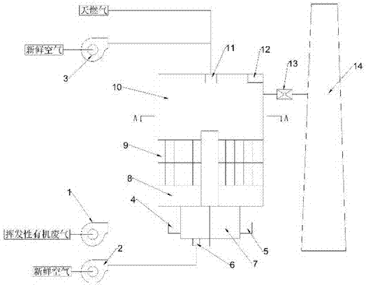
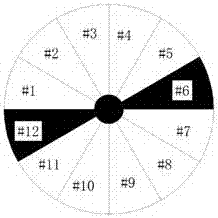
[0020] A tank-type regenerative incinerator, including a system fan 1, a reverse blower 2, a combustion-supporting fan 3, an airflow reversing valve 7, a buffer chamber 8, a regenerator 9, a combustion chamber 10, a burner 11, an electric thermocouple 12, a high temperature Smoke valve 13, chimney 14 and industrial control system. The main body of the tank-type regenerative incinerator is mainly composed of a regenerator 9 and a combustion chamber 10. The regenerator 9 is a cylindrical structure, and the upper and lower ends are not sealed. The inner wall of the steel cylinder is provided with an insulation layer. Evenly divided into 12 independent heat storage spaces #1--#12, each space is equipped with a honeycomb ceramic heat storage body; the combustion chamber 10 is also a cylindrical structure, the upper end is sealed, and the lower end is open. The upper end of the regenerator 9 is butted, the combustion chamber 10 is provided with the burner 11, the thermocouple 12 and...


PUM


Abstract

The invention relates to a tank-type regenerative incinerator, including a system fan, a reverse blower, a combustion-supporting fan, an airflow reversing valve, a buffer chamber, a regenerator, a combustion chamber, a burner, an electric thermocouple, a high-temperature flue gas valve, a chimney and industrial control system. It overcomes the problem that there is no backflush space in small equipment, resulting in the discharge of untreated waste gas, by setting 12 independent spaces in the regenerator and buffer chamber, which contain a backflush space and an empty space; and by regularly replacing the above spaces, The equipment can also be rested during operation, so as to ensure the repeated operation of the entire equipment, reduce the loss of production stoppage caused by equipment rest and prolong the life of the equipment.

Description

technical field [0001] The invention relates to the field of environmental protection, in particular to waste gas treatment equipment. Background technique [0002] At present, the most common and effective treatment process for volatile organic waste gas is the regenerative incinerator. The existing organic waste gas regenerative incinerators are generally divided into two-chamber, three-chamber or five-chamber types. The structure of the two-chamber regenerative incinerator is simple. Since there is no blowback system, some untreated organic waste gas will be discharged when the reversing valve is switched, so the treatment efficiency of the two-chamber regenerative incinerator is low (90%-95%); The three-chamber and five-chamber thermal storage incinerators have high treatment efficiency (99%), but the structure is complex, the equipment is bulky, the installation and maintenance are troublesome, and the failure rate is high. Contents of the invention [0003] In order...

Claims


Application Information

Patent Timeline
IPC IPC(8): F23G7/06F23G5/50
CPCF23G7/066F23G5/50
Inventor 欧文刚尹镇强
Owner 江苏众明环保科技有限公司
Why Eureka
Try Eureka